44473001TH Rev.1
116 /
Oki Data CONFIDENTIAL
4.REPLACEMENT OF PARTS
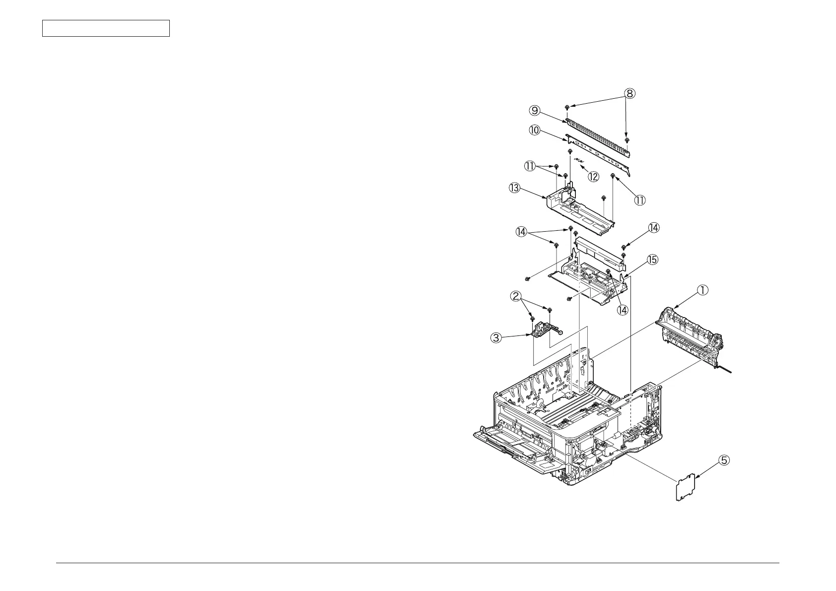
4.2.17 Guide-ejection assembly, fuser connector
assembly and color-registration assembly
(1) Remove the left side cover, the right side cover, the rear cover and the top cover
assembly.
(2) Remove the CU/PU PCB and the low-voltage power supply.
(3) Detach the guide-ejection assembly
①
.
(4
) Remove the two (silver-colored) screws
②
to detach the fuser connector assembly
③
.
(5
) Remove the film-PUCU board
④
and the film-power board
⑤
.
(6
) Remove the (silver-colored) screw
⑧
to remove the image drum fan assembly
⑦
.
(7
) Remove the two (silver-colored) screws
⑥
to remove the cover-beam
⑨
and the
plate-beam
⑩
.
(8
) Remove the three (silver-colored) screws
⑪
to remove the two torsion springs
⑫
and then the cover-code
⑬
.
(9
) Remove the four (silver-colored) screws to detach the color-registration assembly
⑮
.


 To Next Page