Page: 44
Service Guide ML390/391
Chapter 3 Maintenance & Disassembly
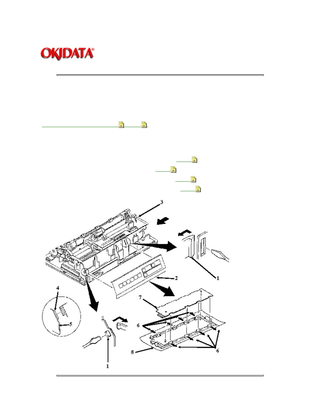
3.2.05 Operator Panel Assembly
NOTE:
The operator panel assembly and board for the Microline 390 and 391 printers are NOT compatible with
the Microline 390-Plus and 391-Plus operator panel assembly and board.
·
Perform this procedure: 3.2.01
,3.2.04 .
· Release the claws (1) and remove the operator panel assembly (2) from the chassis (3). As the operator
panel assembly is removed, it must be detached from the connector (4) on the control board (5).
· Release the eight claws (6) and remove the operator board (7) from the bezel (8).
P/N 50069601 Panel: Operation w/Frame Both RSPL A B C
B.2.08
(Assembly)
P/N 50069610 Panel: Operator Both+ RSPL A B C
B.2.08
P/N 55038605 PCB: LXSP-5 (Operator Panel) Both+ RSPL
B.2.08
P/N 55045601 PCB: LXSP (Operator PCB) Both RSPL A B C
B.2.08