2HA/2HB
2-3-2
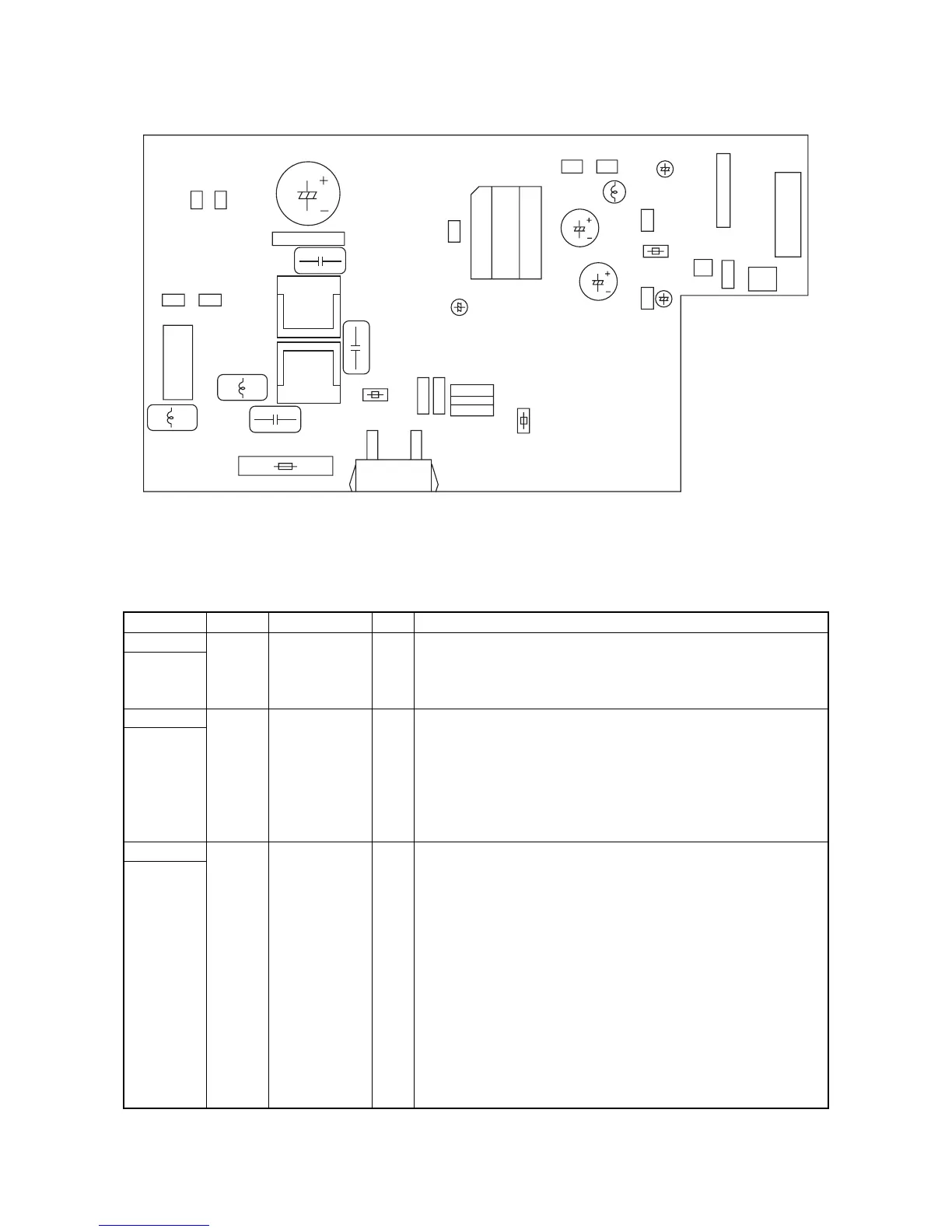
Figure 2-3-2 Power source PWB silk-screen diagram
Connector Pin No. Signal I/O Description
IL001 1 AC-L I AC supply (LIVE)
Connected
to the AC
power plug
2 FG - Ground
3 AC-N I AC supply (NEUTRAL)
YC1 1 +24 V1 O DC power supply for LCSSW
Connected
to the
engine PWB
and left
cover safety
switch
2 NC - Not used
3 +24 V2 I 24 V DC power supply
4 +24 V4 O 24 V DC power supply for EPWB
5 PGND - Ground
6 SGND - Ground
7 +5 V O 5 V DC power supply for EPWB
YC2 1 +5 V O 5 V DC power supply for EPWB
Connected
to the
engine PWB
2 SGND - Ground
3 +24 V2 I 24 V DC power supply
4 SGND - Ground
5 ZCROSS O Zero-cross signal
6 SLEPN I Power source sleep signal
7 S.HEATN I FH-S on/off
8 M.HEATN I FH-M on/off
9 COUNTN I Counter control signal
10 PGND - Ground
11 PGND - Ground
12 +24 V1 O 24 V DC power supply for EPWB
13 +24 V1 O 24 V DC power supply for EPWB
14 +24 V O 24 V DC power supply for EPWB
PC005
PC004
TR001
TR002
L013
L001
L003
L004
C003
F001
F002
C027
YC8
L012
F003
F201
D101
Q101Q206
YC7
C006
T001
C102
C017
C301
IC301
C204
L102
C104
YC2
YC1
1
1
1
1
1
1
3
1
1
44
2
2
2
14
7
YC3 YC5
YC9
Q006
D005
C008
SW001
YC6
 Loading...