EasyManuals Logo

Olivetti d-Copia 2000 Service Manual

Olivetti d-Copia 2000
242 pages
To Next Page IconTo Next Page
To Previous Page IconTo Previous Page
Page #185 background imageLoading...
Page #185 background image
2HA/2HB
2-3-1
2-3 Operati on of the PWBs
2-3-1 Power source PWB
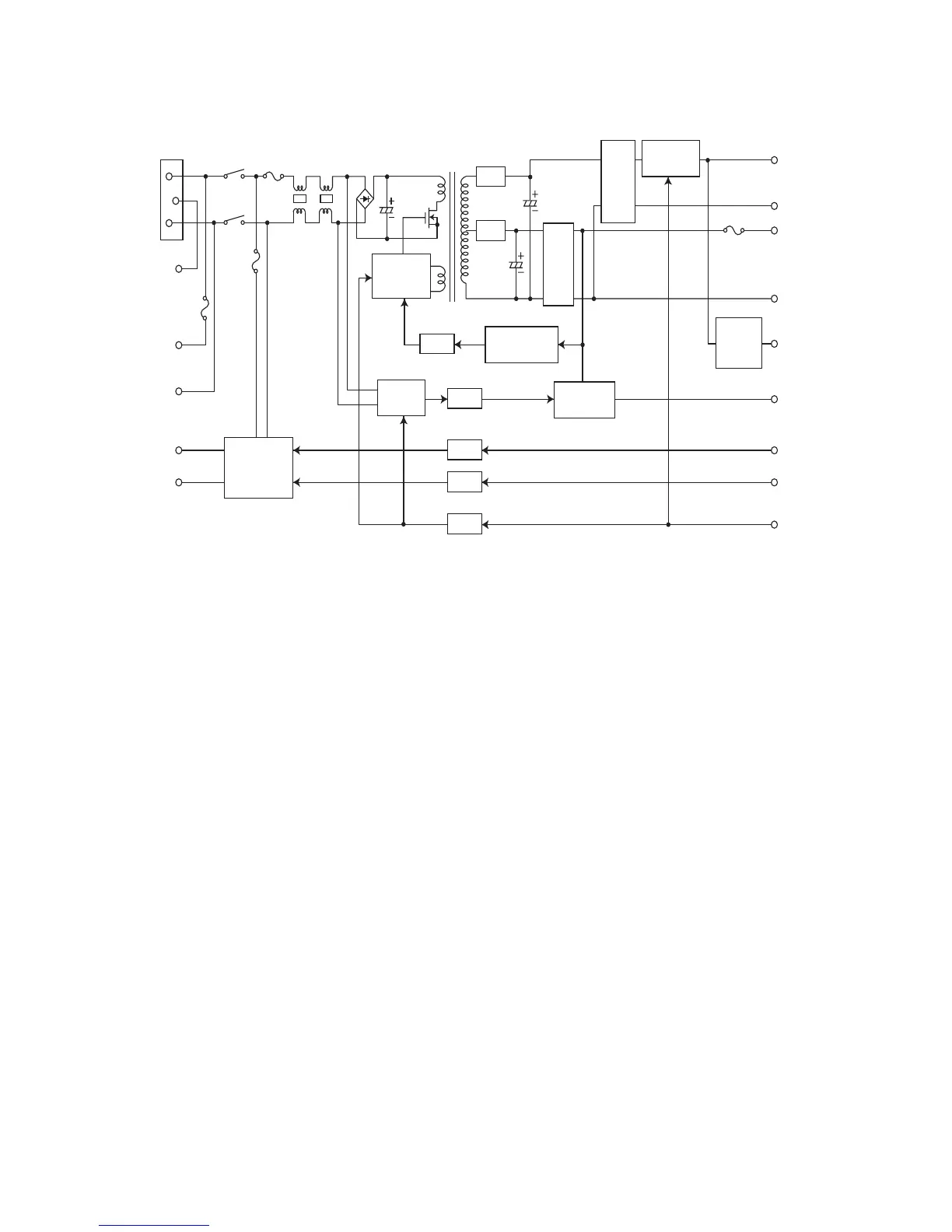
Figure 2-3-1 Power source PWB block diagram
The power source PWB (PSPWB) is a switching regulator that converts an AC input to generate 24 V DC and 5 V DC. It
includes a rectifier circuit, a switching regulator circuit, a 24 V DC output circuit, a 5 V DC output circuit, overvoltage detec-
tion circuit, zero-cross circuit and a fuser heater control circuit.
IL001
FG
D
H1.LIVE
D
H2.LIVE
D
H1.OUT
D
H2.OUT
SH.OUT
Fuser heater
ON/OFF circuit
MH.OUT
AC
INPUT
(TR001,TR002)
Fuser heater
control circuit
Zero-cross circuit
Rectifier circuit
Energy save control circuit
PC001
D101
D005
T001
L004
L003
F002
F001
F003
SW001
C102
F201
C008
C204
Q006
D206
PC002
PC004
PC005
PC003
AC
detection
circuit
Zero-cross
output circuit
ON/OFF
switch circuit
+24V
GND
GND
+5V
+5V1
ZCROS
S
S.HEAT
N
M.HEAT
N
SLEPN
Switching
control circuit
(IC001)
Overvoltage
detection circuit
DC5V
output
circuit
DC5V
3 terminal
regulator
DC24V
output
circuit
(IC201)
(IC301)

Table of Contents

Other manuals for Olivetti d-Copia 2000

Questions and Answers:

Question and Answer IconNeed help?

Do you have a question about the Olivetti d-Copia 2000 and is the answer not in the manual?

Olivetti d-Copia 2000 Specifications

General IconGeneral
BrandOlivetti
Modeld-Copia 2000
CategoryCopier
LanguageEnglish

Related product manuals