2HA/2HB
1-2-11
3. Remove the rear cover.
4. Cut out the aperture plate on the right cover
using nippers.
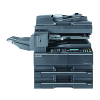
5. Connect the 4-pin connector of the key
counter wire (located at a longer distance
from the tube) to YC13 on the engine PWB,
pass the wire through the two clamps, and
pull the other 4-pin connector out from the
aperture of the right cover.
Arrange the key counter wire behind the
optical system wire as shown in the illustra-
tion.
6. Fold the 7-pin connector of the key counter
wire back, pass the wire through the clamp
at the upper part of the controller box, and
hang it.
Figure 1-2-12
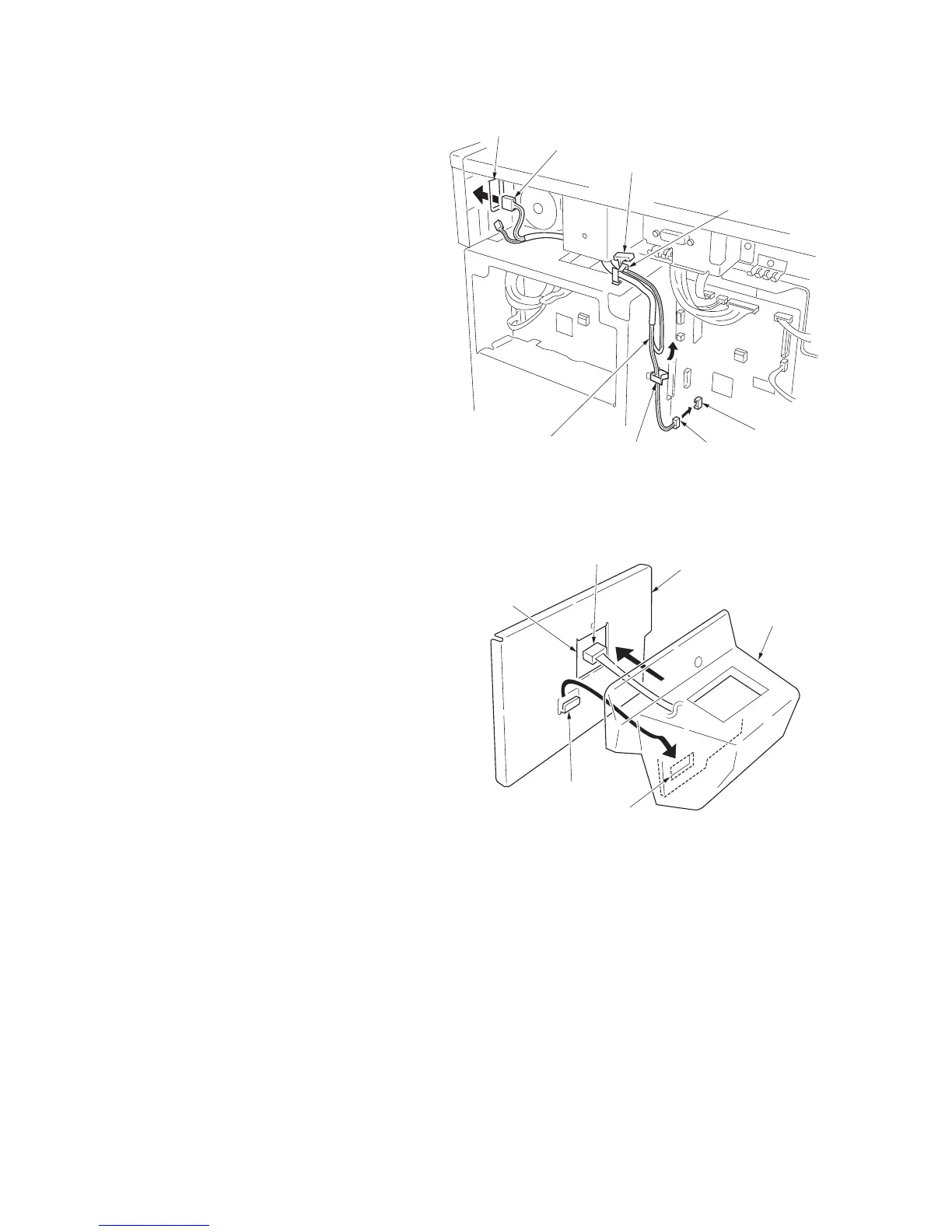
7. Pass the connector of the key counter
through the aperture of the key counter
mounting plate, and engage the projection
of key counter mounting plate with the
square hole of the key counter cover.
Figure 1-2-13
Aperture
YC13
Key counter wire
Clamp
7-pin connector
4-pin connector
4-pin connector
Clamp
Projection
4-pin connector
 Loading...