INSTALLING
OPTIONAL
MODULES
This appendix allows you to file any installation reference booklets for
optional modules. Before installing such modules you should make a
note
of
the current switch settings
on
the card which you will find
in
the pocket inside the back cover of this manual. This card should then
be
affixed to the casing of the system's module.
SWITCH SETTINGS
Switches in the M24 system are set to reflect the addition of memory
and other installed options. Switches are located
on
the motherboard.
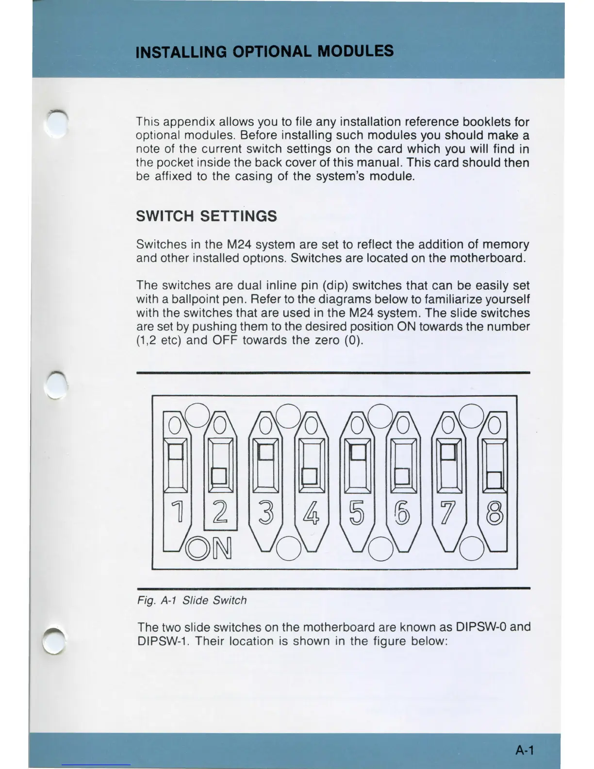
The switches are dual inline pin (dip) switches that can be easily set
with a ballpoint pen. Refer
to
the diagrams below to familiarize yourself
with the switches that are used
in
the M24 system. The slide switches
are
set
by
pushing them
to
the desired position ON towards the number
(1,2 etc) and OFF towards the zero (0).
Fig.
A-1
Slide Switch
The two slide switches
on
the motherboard are known as DIPSW-0 and
DIPSW-1
. Their location
is
shown in the figure below:
A-1