ESG-400
2-7 Checking the current and power consumption and output waveform
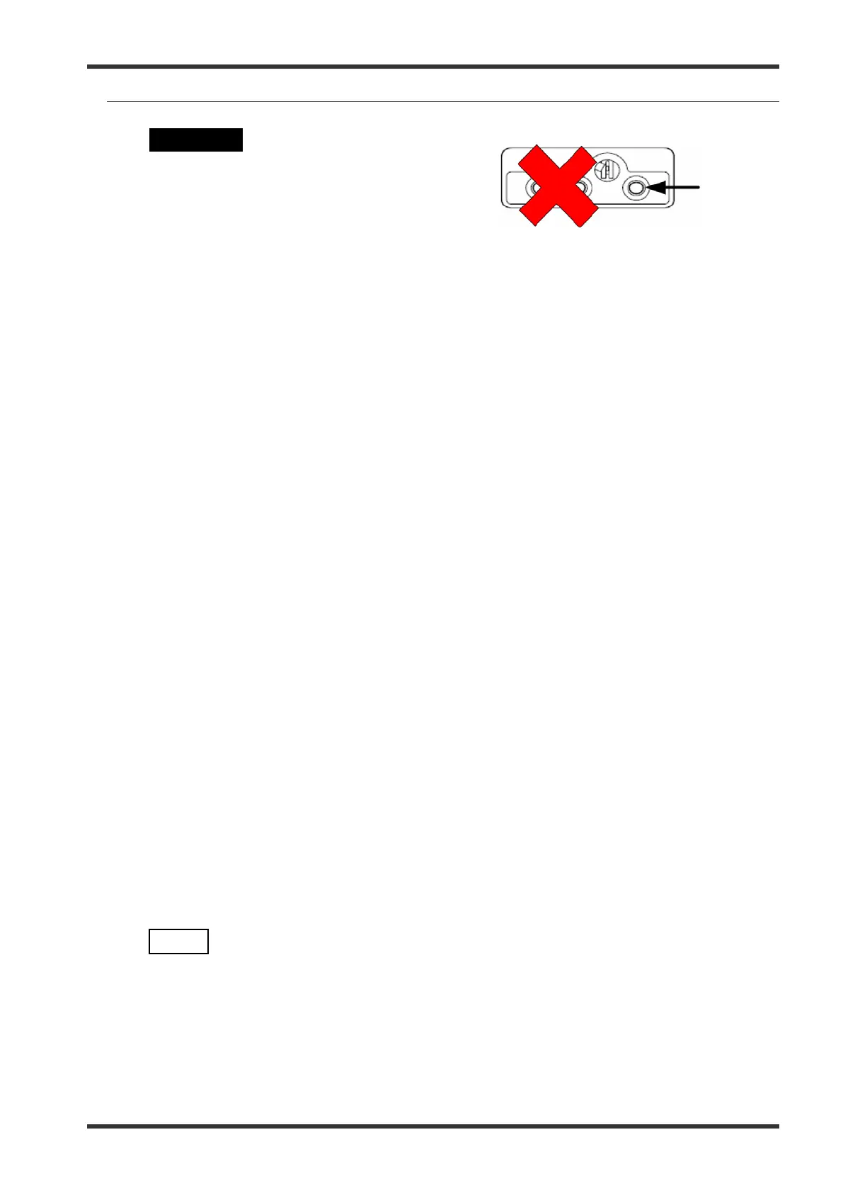
CAUTION
A connection of a 4 mm plug to any
other receptacle except
the right-hand-side receptacle of
the MONOPOLAR 1 socket and
the MONOPOLAR 2 socket may destroy
the socket during activation.
1) Connect the load resistor R
L
= 500 Ω (J005) via a 4mm cable “banana” (J007) to the right receptacle of
the MONOPOLAR 1 socket and via the connection cable “P-cord” (J011) to the neutral socket in the front
panel.
2) Cable the electrosurgical generator with the electrical safety tester according to the testers instructions for
use. Activate the function to measure current and power consumption.
3) Switch the electrosurgical generator on and select the PureCut (Effect 3) mode at the MONOPOLAR 1
socket. Set the level to 300. Assign the footswitch to the MONOPOLAR 1 socket. (Perform the setting
according to the instruction for use.)
4) Activate the output power by pressing “CUT” at the footswitch.
5) Verify the current consumption I
L
is ≤ 10 A.
6) Connect high voltage probe to oscilloscope and to generator output socket (signal to right receptacle of
the MONOPOLAR 1 socket and signal ground to neutral socket)
• Recommended oscilloscope settings:
o Channel 1: high voltage probe 1000:1, DC, 200 V/div (minimum total voltage range
displayed on oscilloscope: -700 V … +700 V)
o Time:
minimum 2 ms/div (minimum total time range displayed on oscilloscope:
20 ms)
maximum 5 ms/div (maximum total time range displayed on oscilloscope:
50 ms)
7) Activate the output power by pressing “CUT” at the footswitch. Record the waveform in the time range
after the high power cut support pulse (ca. 100 ms after HF output start) in steady state.
8) Verify output waveform:
The amplitude level of the output voltage must be stable. No oscillation in the frequency range of
50 … 200 Hz. A maximum amplitude fluctuation from minimum peak voltage to maximum peak voltage of
110 V is allowed for steady state.
NOTE
Table 7.4 is showing good and bad examples how the output waveform should
look like. From the figures in this table it is also clear to see, which parameter
is to be measured.
9) Disconnect high voltage probe.
10) Connect the load resistor R
L
= 75 Ω (J005) via the connection cable (J008) with the UNIVERSAL socket in
the front panel.
7.022.211 / ISSUE 5 84 / 110 Chapter 5: Inspection






 To Next Page