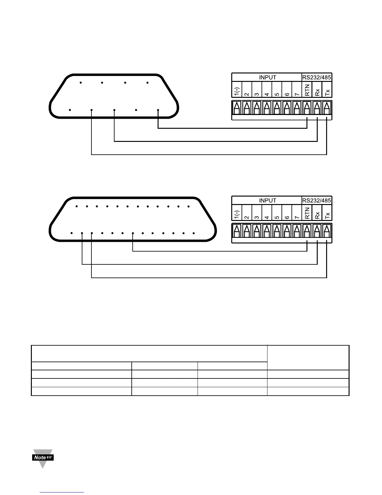
Figures 3.1 and 3.2 show the three-wire RS-232 connections between the host computer
using a 9-pin or 25-pin “D” connector and the i–Series device.
Figure 3.1 Wiring between DB9 computer connector and RS-232 controller interface
Figure 3.2 Wiring between DB25 computer connector
and RS-232 controller interface
Table 3.2 shows the pin connection assignments between the RS-232 connector on the
meter and the 9-pin or 25-pin “D” connectors of your computer.
Table 3.2 Wiring RS-232 Interface
COMPUTER i-SERIES
FUNCTION/
PIN FUNCTION DB9 DB25 LABEL
Receive (Rx) 2 3 Transmit (Tx)
Transmit (Tx) 3 2 Receive (Rx)
Common ground 5 7 RTN
3.3 Wiring RS-485 Interface
RS-485 interface uses a two wire communication system (one for transmitting and one
for receiving) plus a common wire to connect to the shield of a cable. It is recommended
to use a shielded cable with one twisted pair.
Use of twisted pair and shield will significantly improve noise immunity.

 Loading...


