5.7.6 Alarm 1 Low (Command Index 12)
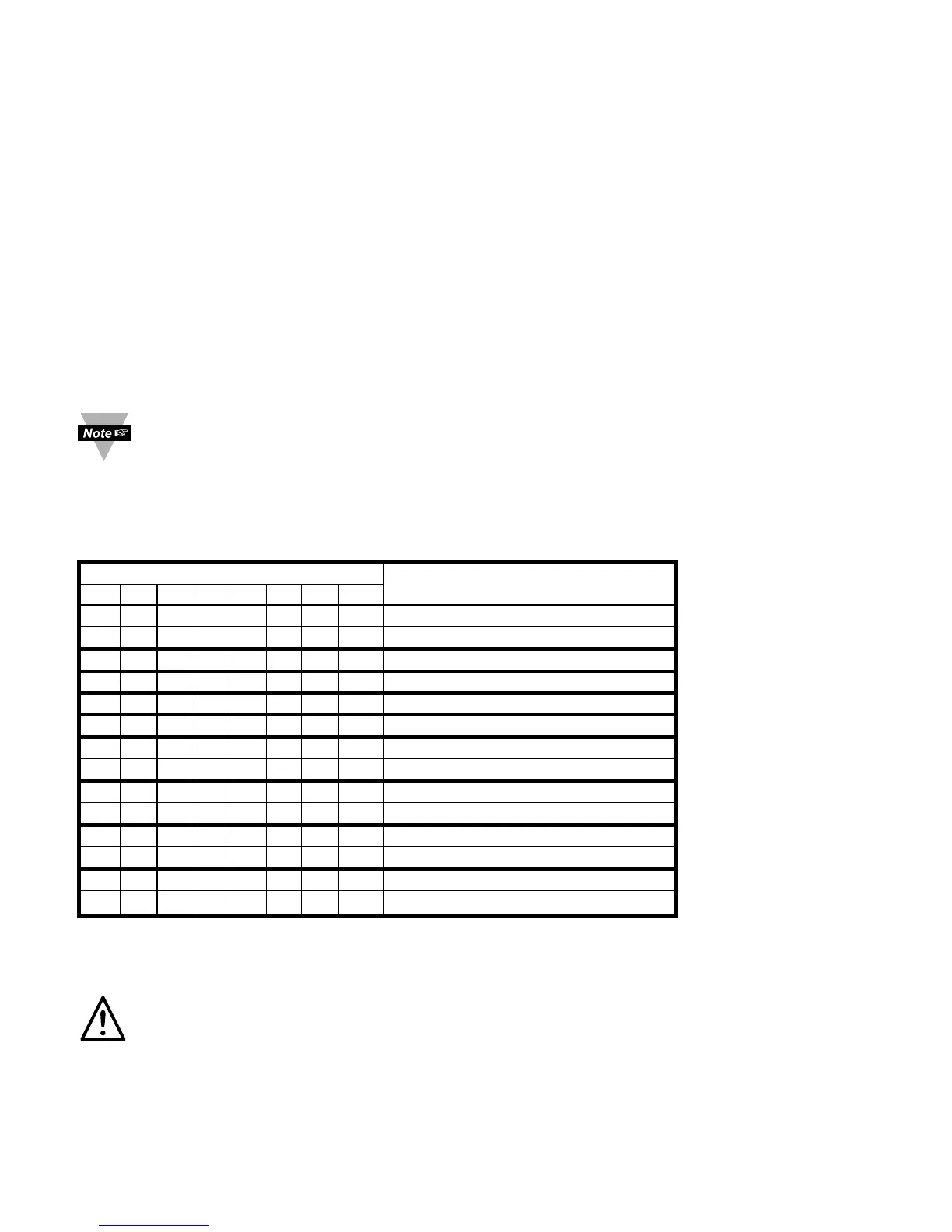
Description: AL1LO.23~0 means 3 bytes x 8 bit positions of the Alarm Low Data
AL1LO.23 = AL1LO.22~20 = AL1LO.19~0 =
0 = positive sign 000 – Not Allowed Setpoint data
1 = negative sign 001 – Decimal Point 1 (FFFF.)
010 – Decimal Point 2 (FFF.F)
011 – Decimal Point 3*(FF.FF)
101 – Decimal Point 4*(F.FFF)
*Process only
Example:Set Alarm 1 Low value to -50.0
The command data is 101000000000000111110100Bin = A001F4Hex.
Send: *W12A001F4
To set the Decimal Point for proper position see command format for RDGCNF
(command index 08).
5.7.7 Alarm 2 Configuration (Command Index 0A)
Description: ALR2CNG.76543210 means 8 bit positions of the Command Data.
BIT NUMBER FUNCTION
76543210
0 Voltage Retransmission
1 Current Retransmission
0 0 Active Above
0 1 Active Below
1 0 Active Hi/Lo
1 1 Active Band (Deviation only)
0 Normally Open
1 Normally Closed
0 Unlatch
1 Latch
0 Absolute
1 Deviation
0 Disable
1 Enable
Example: Set Alarm 2 Enable, Absolute, Latch, N.O.,Above, Current Retransmission.
The command data is 10000101 Bin = 85Hex. Send: *W0A85
Warning: If you change the “0A” to “00” on units with Isolated Analog Output it
will disable the Alarm 2 menu.
26

 Loading...


