PART 3
HARDWARE
3.1 Communication Interfaces
Two communication interfaces are supported in the i-Series devices: RS-232 and
RS-485. These standards define the electrical characteristics of a communication
network.
• The RS-232 standard (point-to-point) allows a single device to be connected to a PC.
The i-Series devices operate with full-duplex RS-232 using three wires: a Rx - receive
wire, a Tx - transmit wire and a common ground wire. RS-232 cable length is limited to
50 feet.
• The RS-485 standard (multipoint) allows one or more devices to be connected
(multi-dropped) using a two wire connection (half-duplex) +Rx / +Tx and -Rx / -Tx.
Use of RS-485 communications allows up to 32 “remote” devices to connect to the
“master” computer with cable length up to 4000 feet long.
• Both interfaces use standard RS-232/RS-485 voltage levels.
Although the RS-485 is commonly referred to as a “two wire” connection, the
i-Series also provides a ground / return shield connection to use as a common
connection for EMI noise protection.
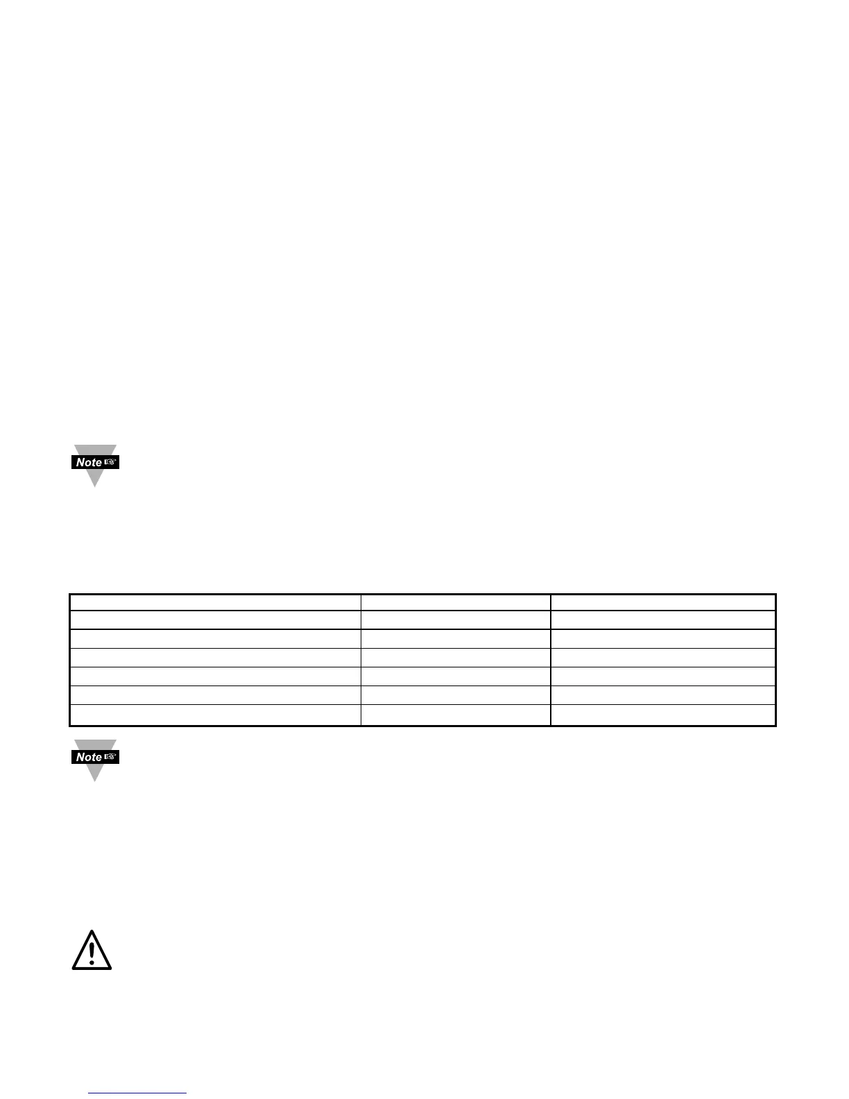
The Table 3.1 shows the differences between RS-232 and RS-485 communication
interfaces.
Table 3.1 Communication Interfaces
Data Transmission Characteristics RS232 RS485
Transmission Mode Single ended Differential
Electrical connections 3 wire 2 wire
Drivers per line 1 driver 32 drivers
Receivers per line 1 receiver 32 receiver
Maximum data rate 20k bits/s 10M bits/s
Maximum cable length 50 ft (15 meters) 4000 ft (1200 meters)
Changing between RS-232 and RS-485 is possible through front panel buttons
(see Part 4 for details).
3.2 Wiring RS-232 Interface
Most PC’s provide an RS-232 port for digital communication. The RS-232 communication
uses three wire full-duplex system: a line for receiving data, a line for transmitting data
and a common line between the computer and device. Usually PCs use a 25 or 9 pin
connector.
Caution: Do not connect power to your instrument until you have completed all
serial interface connections. Failure to do so may result in injury.
5

 Loading...


