30
5.7.14 % Low and % Hi (Command Indexes 27 and 28)
Make sure the values of % Low and % Hi submenus are entered correctly
(% Hi can’t be more than 99% or % Hi should be always more than % Low). If
values entered incorrectly, instrument will reset these values to factory defaults
(% Low = 0, % Hi = 99 (63 Hex)
5.7.15 Reading Scale and Offset (Command Indexes 14 and 3A)
Description: RDGOFF.23~16, 15~8, 7~0 means 3 bytes x 8 bit positions of the
Reading Offset
RDGSC.23~16, 15~8, 7~0 means 3 bytes x 8 bit positions of the
Reading Scale
RDGOFF.23 = RDGOFF.22~20 = RDGOFF.19~0 =
0 positive offset DP+2 offset data
1 negative offset
RDGSC.23~20 = RDGSC.19 = RDGSC.18~0 =
DP+1 0 direct scale scale data
1 reverse scale
Example: To have an input of 4 to 20 mA displayed as 0 to 100
First make sure that Decimal Point on your device is set to the proper position.
Then, disregard the decimal point position through Scale and Offset calculation.
For instance: to display 0 to 100 set decimal point into position 1 (FFFF);
to display 0 to 100.0 set decimal point into position 2 (FFF.F)
then, perform Scale and Offset calculation to display 0 to 1000.
The Low input value = min. input value * conversion number = 4(mA) x 500 = 2000
The High input value = max. input value * conversion number = 20(mA) x 500 = 10000 (9999)
where: conversion number is a coefficient of conversion between input values and real
display range.
The full range of the display = 10000, conversion number = 10000/20 = 500
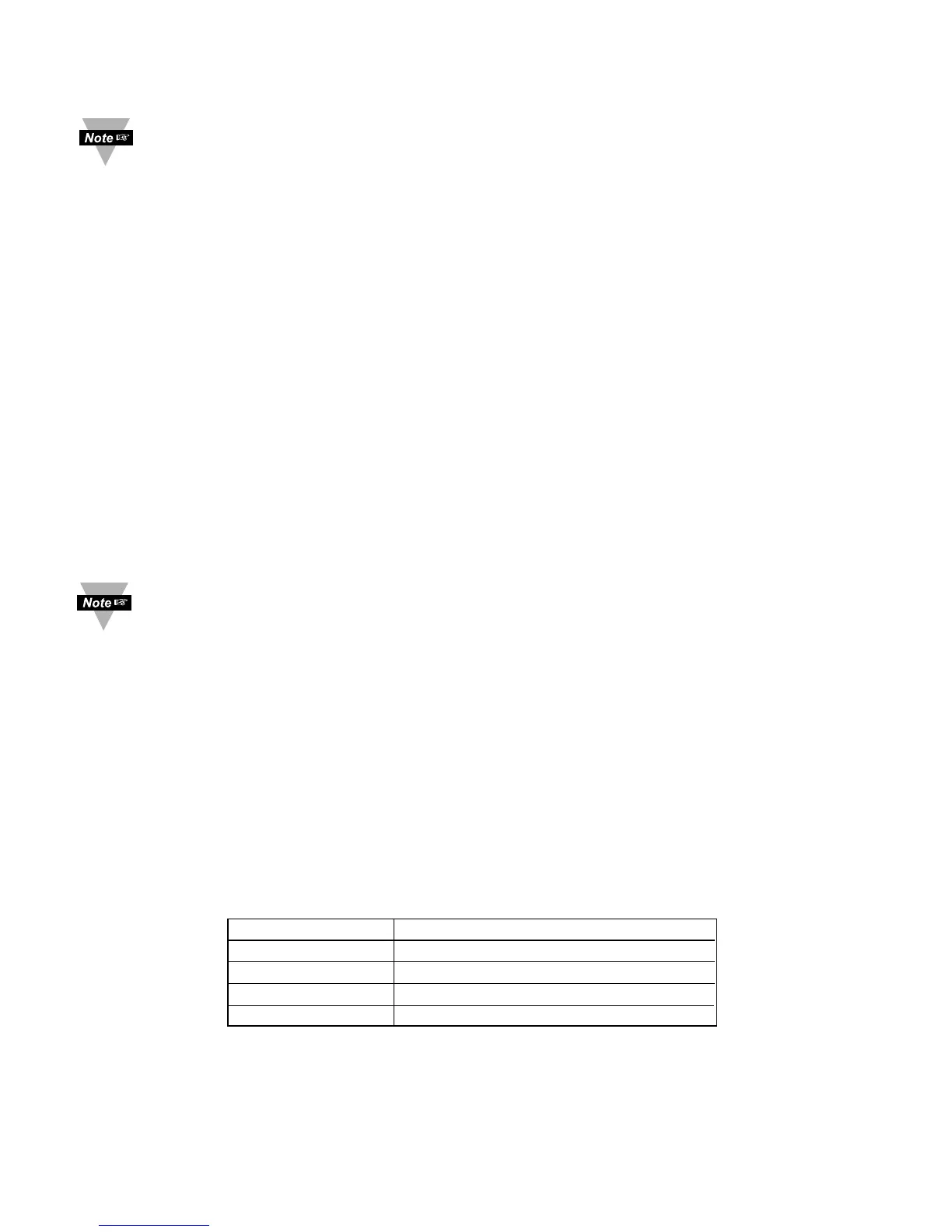
See Table 5.9 below for proper conversion number
Table 5.9 Conversion Number
INPUT RANGE CONVERSION NUMBER
0 ~ 100 mV 10000 / (100 x 1) = 100 cts/mV
0 ~ 1 V 10000 / (1000 x 1) = 10 cts/mV
0 ~ 10 V 10000 / (1000 x 10) = 1 cts/mV
0 ~ 20 mA 10000 / (20 x 1) = 500 cts/mA
 Loading...


