5.2 Command Formats
Table 5.2 shows the command formats for i-Series devices.
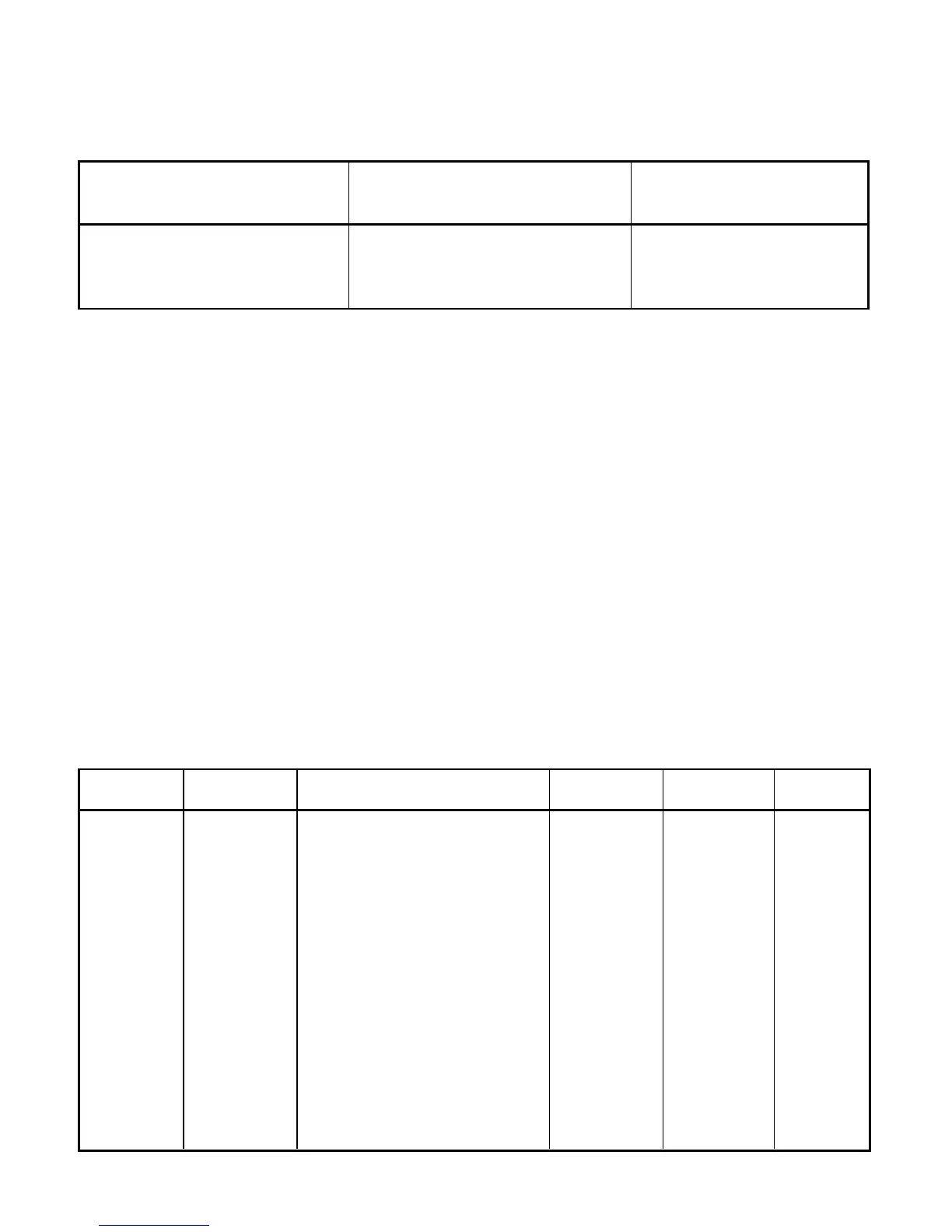
Table 5.2 Command Formats
For “P” and “W” Command For “G” and “R” Command For “X”, “V”, “U”, “D”,
classes: classes: “E”, and”Z” Command
classes:
Point-to-point mode Point-to-point mode Point-to-point mode
* ccc<data><cr> * ccc <cr> * ccc <cr>
Multipoint mode Multipoint mode Multipoint mode
* nnccc [<data>]<cr> * nnccc <cr> * nnccc <cr>
Where:
“*” is the selected Recognition Character. You may select any ASCII table symbol from
“!” (HEX address “21”) to the right-hand brace (HEX “7D”) except for the caret “^”, “A”,
“E”, which are reserved for bus format request.
“ccc” stands for the hex-ASCII Command Class letter (one of eleven given in Table 5.1),
followed by the two hex-ASCII Command Suffix characters identifying the meter data,
features or menu items to which the command is directed (given in Table 5.3).
“<data>” is the string of characters containing the variable information the computer is
sending to the meter. These data (whether BCD or binary) are encoded into hex-ASCII
characters, two characters to the byte. Square brackets (indicating optional status)
enclose this string, since some commands contain no data.
“<nn>” are the two ASCII characters for the device Bus Address of RS-485
communication . Use values from “00” to hex “C7” (199 decimal).
Table 5.3 and 5.4 shows the command letters and suffix for i-Series devices.
Table 5.3 Command Letters and Suffix for Temperature/Process and Process/Strain Gauge
Instrument
Command Command Function Command # Of Default
Index Bytes Characters Value
RW 01 SP1 3 6 200000
RW 02 SP2 3 6 200000
GPRW 03 RDGOFF 3 6 200000
RW 04 ANLOFF 3 6 400000
RW 05 ID 2 4 0000
-06 N/A - --
RW 07 INPUT 1 2 04
GPRW 08 RDGCNF 1 2 4A
RW 09 AL1CNFG 1 2 00
RW 0A AL2CNFG 1 2 00
RW 0B LOOP BREAK TIME 2 4 003B
RW 0C OUT1CNF 1 2 00
RW 0D OUT2CNF 1 2 60
RW 0E RAMPTIME 2 4 0000
14

 Loading...


