APPENDIX A
Reading Scale and Offset for Process/Strain Gage Instrument with 10 Linearization
Points (Command Indexes 2B to 33, 34 to 3C, 3D to 45)
Description: RDGOFF.23~16, 15~8, 7~0 means 3 bytes x 8 bit positions of the
Reading Offset
RDGSC.23~16, 15~8, 7~0 means 3 bytes x 8 bit positions of the
Reading Scale
RDGOFF.23 = RDGOFF.22~20 = RDGOFF.19~0 =
0 positive offset DP+2 offset data
1 negative offset
RDGSC.23~20 = RDGSC.19 = RDGSC.18~0 =
DP+1 0 direct scale scale data
1 reverse scale
Example:
The following example assumes load cells with this specification:
Maximum Load: 100 lbs
Output: 3.0 mV/V
Sensor Excitation: 10 Vdc
Maximum Sensor Output = (Output) x (Sensor Excitation) = 3.0 (mV/V) x 10 (V) = 30 mV
Input Value (In) = (Sensor Output) x (Conversion Number) x (Multiplier)
See Tables A.1 and A.2 below for proper Conversion and Multiplier Numbers.
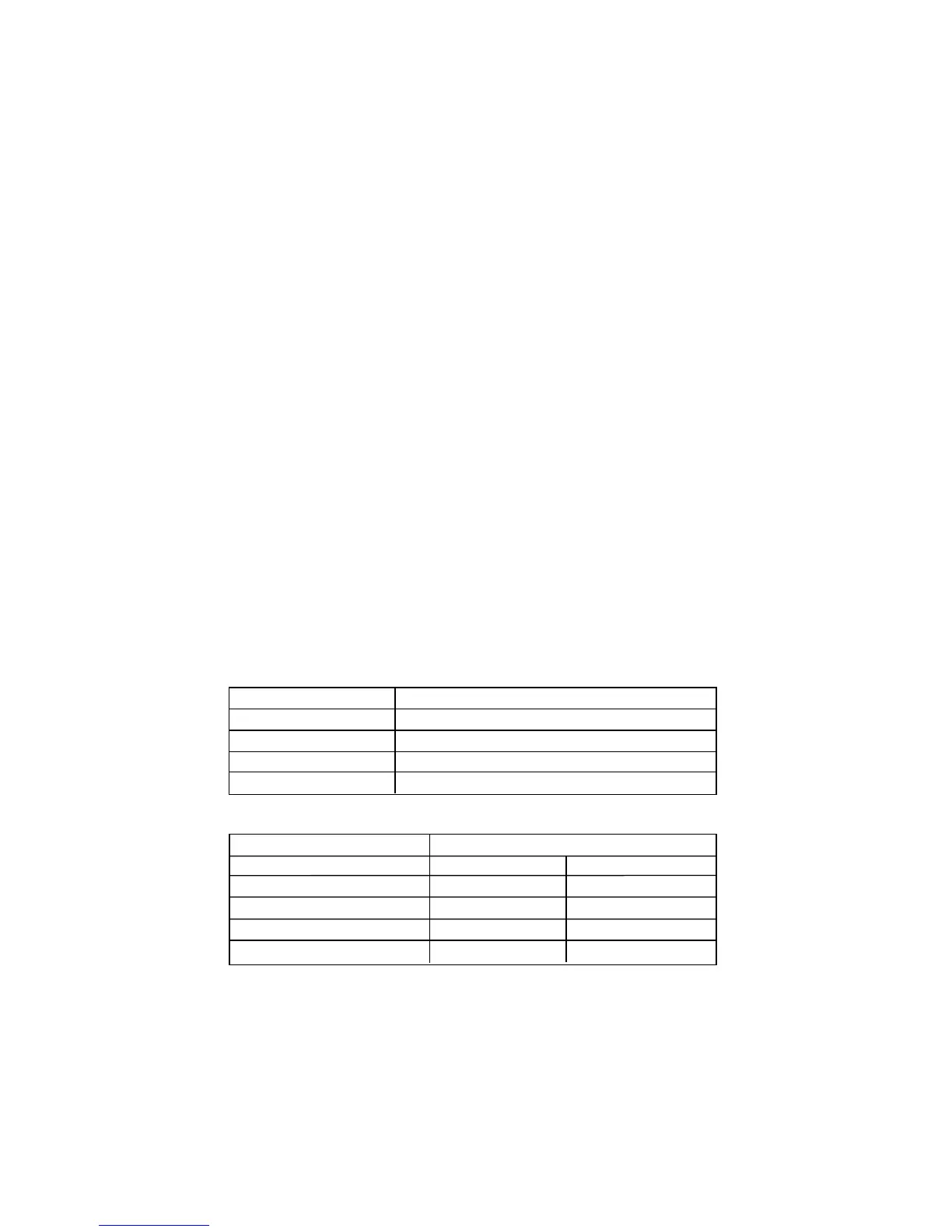
Table A.1 Conversion Number
INPUT RANGE CONVERSION NUMBER
0 ~ 100 mV 10000 / (100 x 1) = 100 cts/mV
0 ~ 1 V 10000 / (1000 x 1) = 10 cts/mV
0 ~ 10 V 10000 / (1000 x 10) = 1 cts/mV
0 ~ 20 mA 10000 / (20 x 1) = 500 cts/mA
Table A.2 Input Resolution Multiplier
INPUT RANGE RESOLUTION
LOW HIGH
0 ~ 100 mV 1.0 10.0
0 ~ 1 V 1.0 10.0
0 ~ 10 V 1.0 10.0
0 ~ 20 mA 1.0 10.0
Determine IN min and IN max Input Range and Resolution. For our transducer select
0 - 100 mV range and Low resolution.
IN min = 0 (mV) x 100 (cts/mV) x 1.0 = 0
IN max = 30 (mV) x 100 (cts/mV) x 1.0 = 3000
43

 Loading...


