© 2011 Omnicell, Inc. External Return Bin Installation and Service Guide/67-2038 Rev D
Installation Instructions 2-13
Installation on G3 Cabinets
4. Remove the second AUX cable connector.
Figure 2-33. Removing the other Aux connector
5. Unplug the 4-pin connector from J24 (labeled AUX) on the PowerCom board, then remove
the cable.
Figure 2-34. Unplugging the 4-pin connector
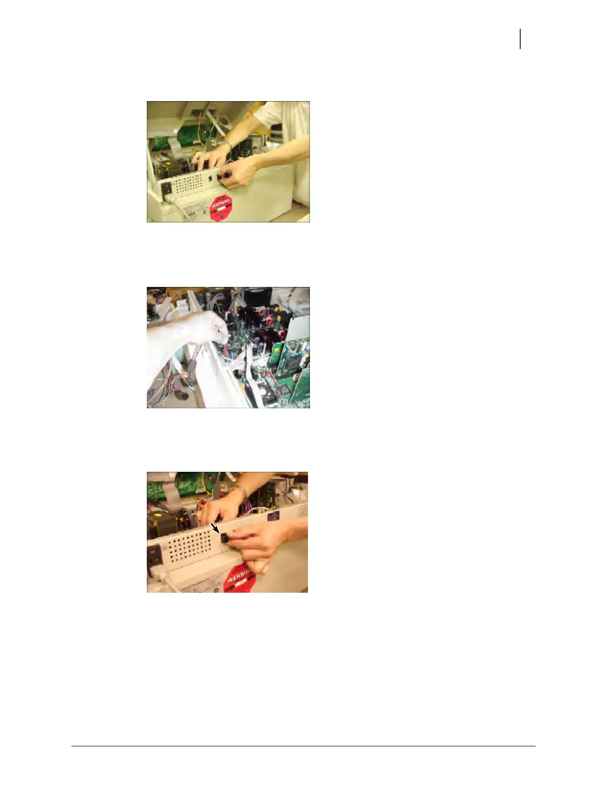
6. Insert the black AUX connector from the External Return Bin retrofit cable assembly
(#42-7052) into the first opening.
Figure 2-35. Inserting the AUX connector from the ERB cable assembly