2-14 Installation Instructions
Installation on G3 Cabinets
External Return Bin Installation and Service Guide/67-2038 Rev D © 2011 Omnicell, Inc.
7. Plug in the 4-pin header connector on the retrofit AUX cable assembly into J24 (labeled AUX)
on the PowerCom board.
Figure 2-36. Plugging in the 4-pin connector
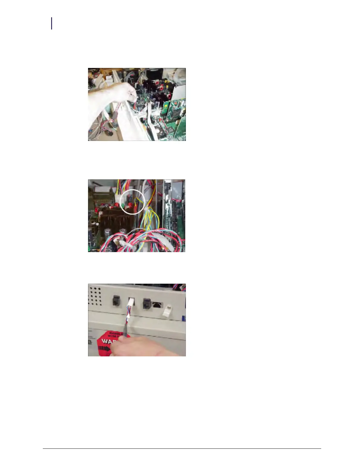
8. Plug in the 3-pin connector with the blue and yellow cables on the retrofit AUX cable assembly
into J16 (labeled MAG) on the PowerCom board.
Figure 2-37. 3-pin connector location
9. Thread the ERB cable connector (white) through the second AUX opening.
Figure 2-38. Threading the ERB cable connector