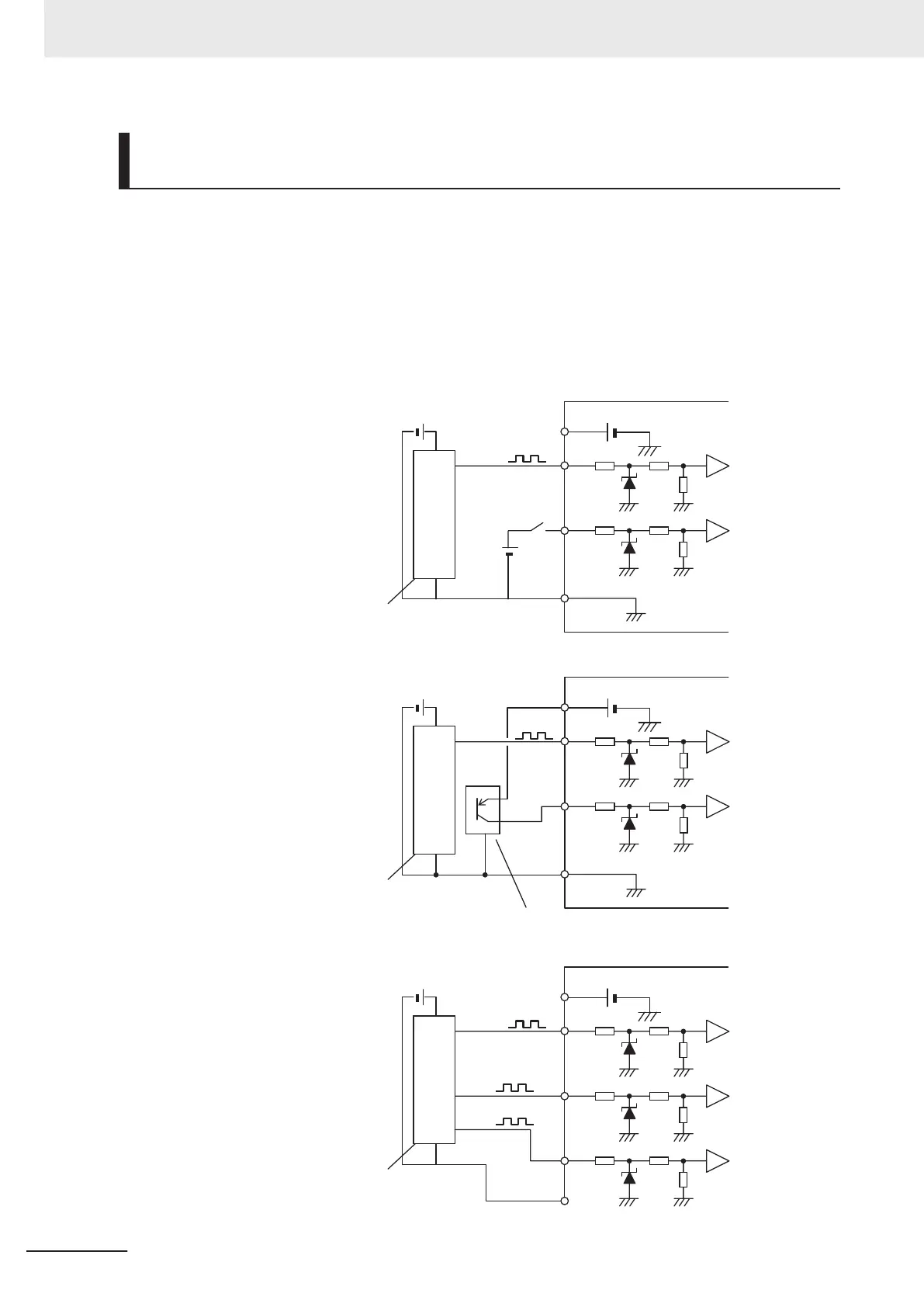
Wiring for Single-phase Pulse Signal and Direction Signal
(3014Hex-0FHex = 0)
Connect the single-phase pulse signal or single-phase pulse + direction signal as shown in the dia-
gram below.
•
Connect the direction signal to the pulse train input PIA terminal and the single-phase pulse to the
pulse train input PIB terminal.
• The +24 V terminal of the inverter control circuit terminal block is for a 100 mA maximum 24 V pow-
er supply. This terminal can be used for the encoder power supply if the consumption current for the
input terminals in use and the encoder power supply is allowable. However, note that this terminal
must be isolated from any 24 V system power supply for other than the encoder and inverter.
PIA
+24
PIB
DIC
Vcc
GND
Out
3G3M1
Direction
Complementary-output type
encoder
Encoder
PIA
+24
PIB
DIC
Vcc
GND
Out
3G3M1
Direction
Complementary-output type
encoder
Encoder
Source transistor
PIA
+24
PIB
Vcc
GND
Out
3G3M1
Out
Out
PIZ
DIC
Complementary-output type
encoder
Encoder
2 Design
2-64
M1 Series EtherCAT Type User’s Manual (I670)
 Loading...


