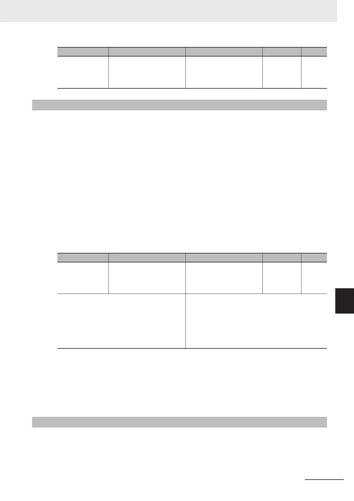
Parameter No. Function name Data Default data Unit
3005Hex-15Hex/
3005Hex-1CHex
Output Terminal [DO1] Func-
tion Selection/Output Terminal
[ROA, ROB] Function Selec-
tion
48: SWM1 (1st motor in oper-
ation)
49: SETM (2nd motor in oper-
ation)
- -
8-8-20
Inverter Output Limiting (IOL, IOL2)
This signal is output when the inverter is performing one of the limitation operations described below.
(Minimum output signal width 100 ms)
The signal is output when the limitation operation in “22: IOL2 (Inverter output limiting with delay)” con-
tinues for 20 ms or longer.
•
Torque limit operation
Torque Limit 1/2/3/4 (3004Hex-29Hex/3004Hex-2AHex/3005Hex-11Hex/3005Hex-12Hex)
• Current limitation operation by software
Overload Protect Function Selection (3004Hex-2CHex/301FHex-2FHex)
Overload Protect Level (3004Hex-2DHex/301FHex-30Hex)
• Current limitation operation by hardware
Instantaneous Overcurrent Limiting Function Selection (3008Hex-0DHex)
• Anti-regenerative control
Anti-regenerative Control Function Selection (3008Hex-46Hex)
• Overload Stop Function
Overload Stop Mode Selection (300EHex-42Hex)
Parameter No. Function name Data Default data Unit
3005Hex-15Hex/
3005Hex-1CHex
Output Terminal [DO1] Func-
tion Selection/Output Terminal
[ROA, ROB] Function Selec-
tion
5: IOL (Inverter output limit-
ing)
22: IOL2 (Inverter output limit-
ing with delay)
- -
Related function
Output T
erminal [DO1] ON Delay Time (3051Hex-0AHex)
Output Terminal [DO1] OFF Delay T
ime
(3051Hex-0BHex)
Output Terminal [ROA, ROB] ON Delay Time
(3051Hex-0EHex)
Output Terminal [ROA, ROB] OFF Delay Time
(3051Hex-0FHex)
The OFF delay becomes the time obtained by adding 0.1 s to Output Terminal [DO1] OFF Delay Time
(3051Hex-0BHex) and Output Terminal [ROA, ROB] OFF Delay T
ime (3051Hex-0FHex).
• When the IOL signal or the ILO2 signal is ON, the output frequency of the inverter is automatically
controlled by the limitation processes described above, and thus, the set frequency may not be ach-
ieved.
8-8-21
Low DC link bus voltage detection (U-EDC)
This signal turns ON when the Main Circuit DC Voltage becomes equal to or below Main Circuit DC
V
oltage low-voltage detection level (3005Hex-4DHex), and turns OFF when it becomes above the
Main Circuit DC V
oltage low-voltage detection level (3005Hex-4DHex).
8 Other Functions
8-93
M1 Series EtherCAT Type User’s Manual (I670)
8-8 Functions Related to Protection, Warning and Various Output Signals
8
8-8-20 Inverter Output Limiting (IOL, IOL2)