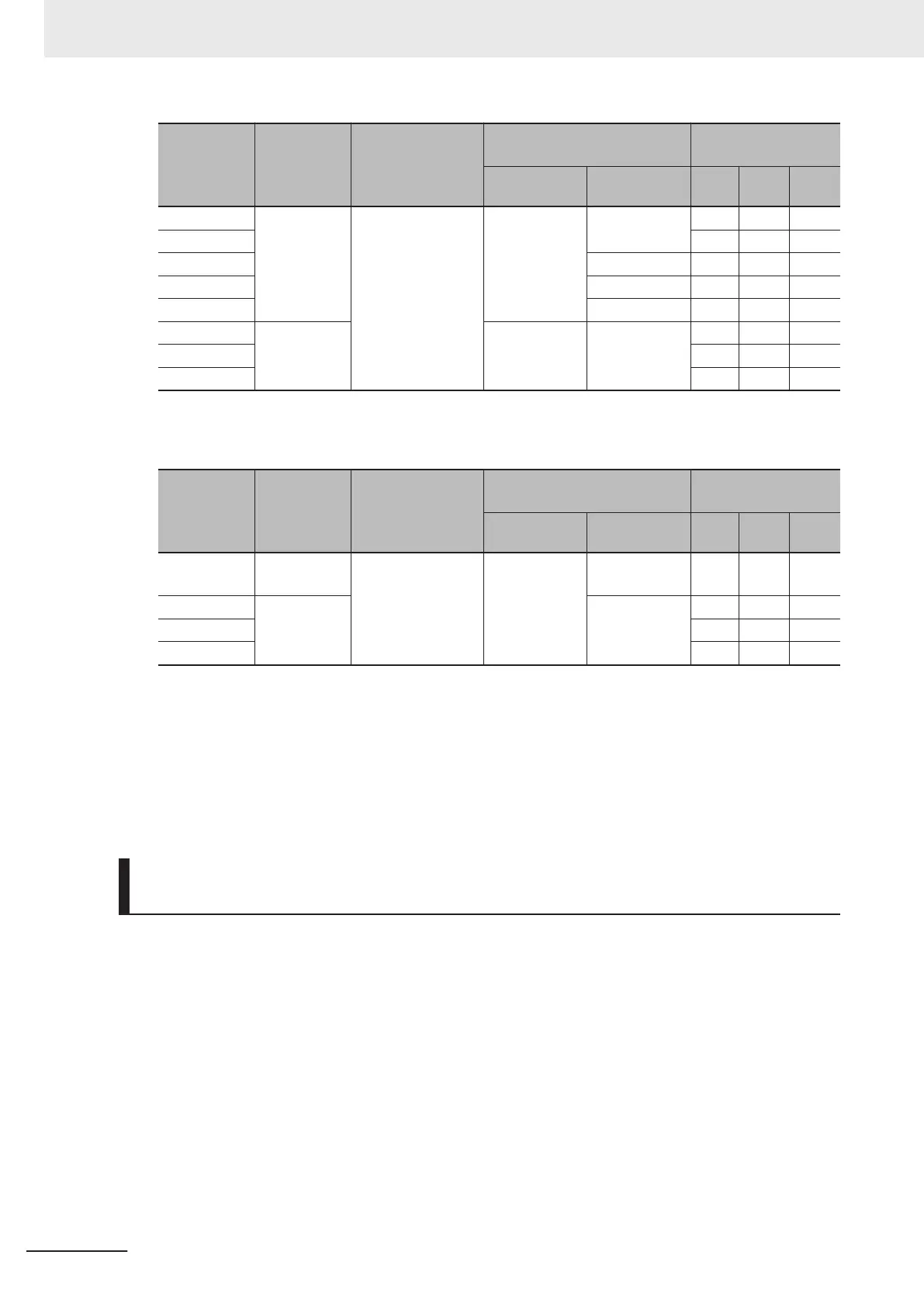
Motor ca-
pacity
Thermal
time con-
stant t (fac-
tory default)
Thermal time
constant setting
reference current
value Imax
Characterization factor
switching frequency
Characterization
factor
f
2
f
3
α1 α2 α3
0.4, 0.75 kw
5 min
Continuous allowa-
ble current value ×
150%
5 Hz
7 Hz
75% 85% 100%
1.5 to 3.7 kW 85% 85% 100%
5.5 to 11 kW 6 Hz 90% 95% 100%
15 kw 7 Hz 85% 85% 100%
18.5, 22 kW 5 Hz 92% 100% 100%
30 to 45 kW
10 min
Base Fre-
quency × 33%
Base Fre-
quency × 83%
54% 85% 95%
55 to 90 kW 51% 95% 95%
110 kw min. 53% 85% 90%
Synchronous motor (PM)
Motor ca-
pacity
Thermal
time con-
stant t (fac-
tory default)
Thermal time
constant setting
reference current
value Imax
Characterization factor
switching frequency
Characterization
factor
f
2
f
3
α1 α2 α3
0.2 to 22 kW 5 min
Continuous allowa-
ble current value ×
150%
Base Fre-
quency × 33%
Base Fre-
quency × 33%
69% 90% 90%
30 to 45 kW
10 min
Base Fre-
quency × 83%
54% 85% 95%
55 to 90 kW 51% 95% 95%
110 kw min. 53% 85% 90%
When Motor Electronic Thermal Characteristic Selection (3004Hex-0BHex/
3009Hex-07Hex) = 2: For an inverter-driven motor non-ventilated motor or
motor with separately powered cooling fan
• The operation level is a constant value without decrease that is set at Motor Electronic Thermal
Level (3004Hex-0CHex/3009Hex-08Hex) as there is no drop in the cooling effectiveness by out-
put frequency
.
Motor Electronic Thermal Time Constant (3004Hex-0DHex/
3009Hex-09Hex)
• Set the thermal time constant of the motor. Set the electronic thermal operating time for when a cur-
rent of 150% of the operation level set at Motor Electronic Thermal Level (3004Hex-0CHex/
3009Hex-08Hex) flows continuously. The thermal time constant of a general motor is 5 minutes for
22kW or less (factory default).
(Example) When the data of Motor Electronic Thermal T
ime Constant (3004Hex-0DHex/
3009Hex-09Hex) is set to “5” (5 minutes)
When a current 150% of the overload detection level set as shown in the figure below flows for 5 mi-
nutes, the motor overload (alarm codes: 17, 18) protection function operates. Also, for 120%, the mo-
tor overload protection function operates after approx. 12.5 minutes.
The time that an alarm actually is generated is shorter than the set data as the time from when the
continuous allowable current (100%) is exceeded up to when the 150% level is reached also is taken
into consideration.
6 Basic Settings
6-20
M1 Series EtherCAT Type User’s Manual (I670)