Test pulse that is input to safety input terminals [SF1] and [SF2] from an external device must be 1 ms
or less.
The following shows an example of a safety interlock that is combined with the 3G3M1 Series.
Model Applicable standard for system configuration Certification authority
G9SP
EN ISO13849-1 PL-e Cat4
(IEC61508 SIL3)
TÜV Rheinland
Periodic Inspection
The redundancy circuit is configured so that when the safety function is activated, the inverter shuts off
its output if current no longer flows to either the safety input terminal [SF1] or [SF2]. Therefore, the
inverter must be periodically inspected to ensure that there is no defect in the [SF1] and [SF2] terminal
wirings so that redundancy is not lost to ensure reliable operation. Be sure to perform periodical in-
spection at least once in three months.
In periodic inspection, inspect the statuses shown in the table below.
Signal Status 1 Status 2 Status 3 Status 4
Input
SF1 OFF ON OFF ON
SF2 OFF OFF ON ON
Output
EDM ON OFF OFF OFF
Output to motor Shut off Shut off Shut off
Output ena-
bled
Alarm None ECF ECF None
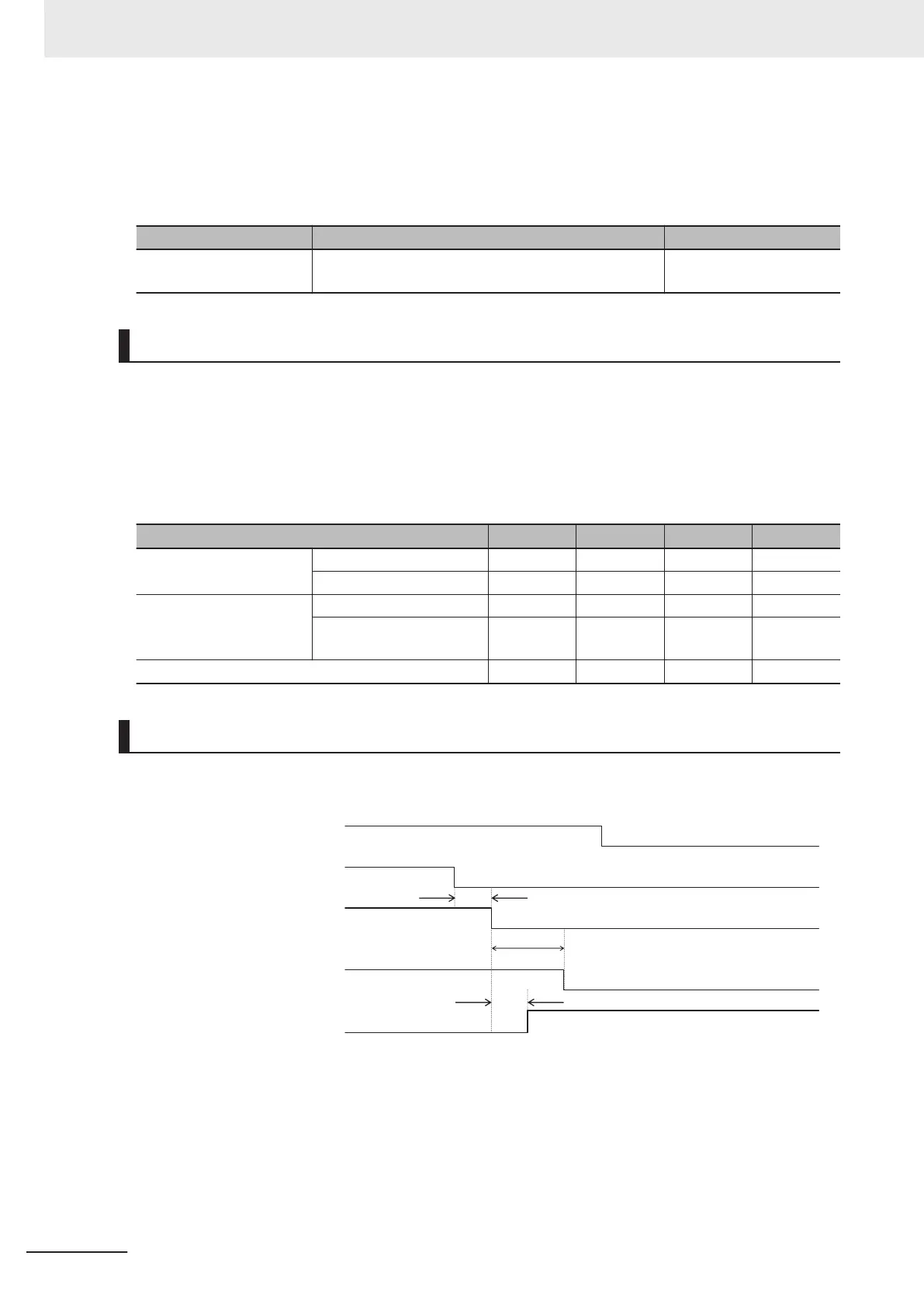
Timing of transition to safety status
When one of safety input terminals [SF1] and [SF2] turns OFF and then both terminals turn OFF within
50 ms, control transitions to the STO state.
Response time within 50 ms
RUN command
Safety input 1 termi
nal [SF1]
Safety input 2 terminal [SF2]
Motor power ON state
EDM output
Normal state
Normal state
on
on
on
off
off
off
STO state
20 ms max.
STO state
50 ms max.
When one of terminals [SF1] and [SF2] turns OFF and then both terminals do not turn OFF within 50
ms, EN circuit failure (alarm code: ECF) is generated.
8 Other Functions
8-64
M1 Series EtherCAT Type User’s Manual (I670)
 Loading...


