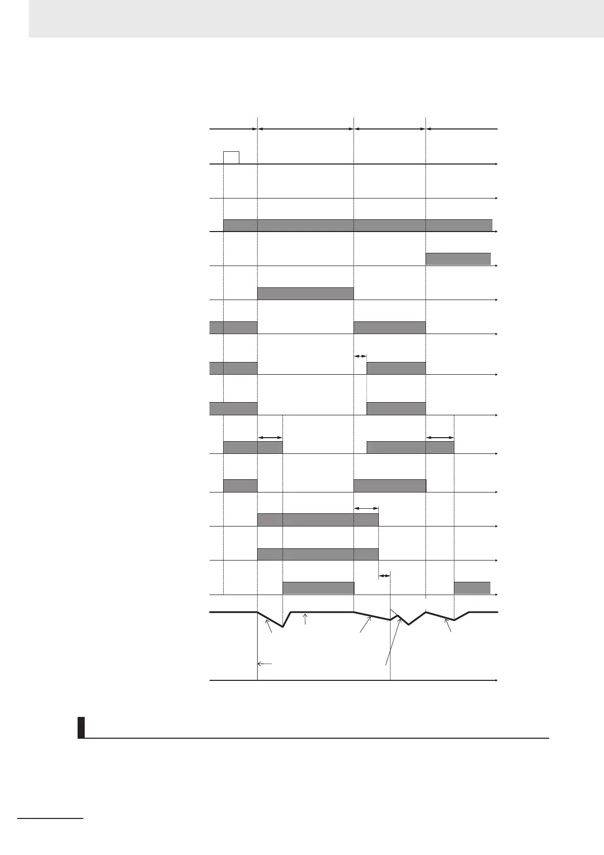
Timing diagram for commercial switching
RUN command
OPX
Alarm
30
Commercial power supply selection
43
Inverter primary side
MC1
Operation SW
3S
Stop SW
5S
ON
ON
ON
ON
ON
ON
ON
ON
ON
ON
ON
ON
ON
ON
ON
Commercial power supply
ON
ON
Inverter
operation Inverter operation
When switching to commercial
power supply due to occurrence of
an alarm during inverter operation
Commercial power
supply operation
↓ Alarm occurrence
InverterInverter
t
t
t
t
t
t
Inverter secondary side
delay timer
T3 (ON delay)
t
Inverter secondary side
MC2
t
Commercial power supply switch
delay timer
T1 (OFF delay)
Forward command
FD
Commercial power supply switch
T2 (OFF delay)
Commercial power supply selection
CS
Commercial power supply circuit
MC3
Inverter output
and motor rotation
t
t
t
t
t
t
T3
T2
3008Hex-0EHex
T1 T1
Motor free-run Motor free-run
Motor free-run
Pull-in
Motor rotation
Inverter output
free-run
N
o
rm
al
acceleration
Input during Commercial Operation (CRUN-M1, CRUN-M2)
If operation is not performed by the inverter during the commercial switching operation, it is possible to
integrate 1st Cumulative Motor Run T
ime (3008Hex-5FHex)/2nd Cumulative Motor Run T
ime
(3009Hex-34Hex) by incorporating the auxiliary contact points of the electromagnetic contactor for
commercial switching to CRUN-M1 and CRUN-M2 allocated to multifunction input as a digital signal.
8 Other Functions
8-128
M1 Series EtherCAT Type User’s Manual (I670)
 Loading...


