• Avoid placing noise-generating cables (such as power cables and motor cables of the inverter) in
parallel with signal cables and allow a clearance of at least 25 cm between them.
If you cannot avoid crossing two types of cables, keep them at right angles to each other.
W
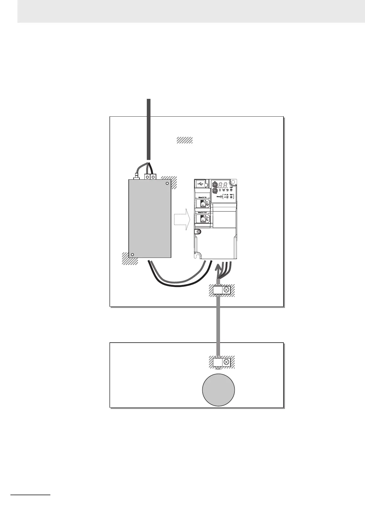
iring example for single-phase 200-V class
Motor
U, V, W
PE
EMC filter
(Foot-print)
L1, N
Ground plate
:Remove the paint
for enhanced contact integrity.
Input power supply
Cable clamp
Cable clamp
Shield braided cable
(20 m max.)
Ground plate
Low-voltage directive (electrical safety)
The 3G3M1 Series Inverter complies with EN61800-5-1 when installed and wired to equipment ac-
cording to the methods described below.
•
The 3G3M1 Series Inverter is an open type device. Be sure to install it inside the control panel.
• The power supply and voltage (SELV) with reinforced or double insulation should be used for wir-
ing to the control circuit terminals.
2 Design
2-70
M1 Series EtherCAT Type User’s Manual (I670)
 Loading...


