8-9-19
Servo Lock Function
The servo lock function is used to control the position of the motor, and continue to retain the position
even when an external force is applied.
It is enabled only during vector control with speed sensor
. The servo lock function is enabled by turn-
ing the LOCK terminal ON.
If operation is stopped even with position control disabled (SPD terminal ON) when the servo lock is
enabled, a deceleration is performed to the stop frequency
, then position control is performed with the
position where the output frequency becomes 0 taken as the target stop position, and then servo lock
is performed.
The servo lock operates at a low speed, and therefore, if it is used by applying an external force over a
long period of time, overheat protection may be activated.
Servo lock is started when all of the following conditions are satisfied.
• RUN command is OFF, or set frequency < stop frequency (3004Hex-1AHex)
• LOCK terminal ON
• [“0: Output frequency, Detected speed” is set for 1st Stop Frequency Detection Method Selection
(F3004Hex-27Hex) and speed detection value is Stop Frequency (F3004Hex-1AHex) or less] or [“1:
Frequency reference” is selected for 1st Stop Frequency Detection Method Selection
(3004Hex-27Hex) and frequency reference value is Stop Frequency (3004Hex-1AHex) or less]
Set the gain for the position control of the servo lock by Servo Lock Gain (J97). The behavior of stop-
ping the inverter during a servo lock, and the axial holding force can be adjusted.
When setting smaller value to J97, the response is delayed, but the behavior becomes smoother and
the axial holding force is reduced. When setting larger value, the response becomes faster, but hunt-
ing increases and the axial holding force also increases.
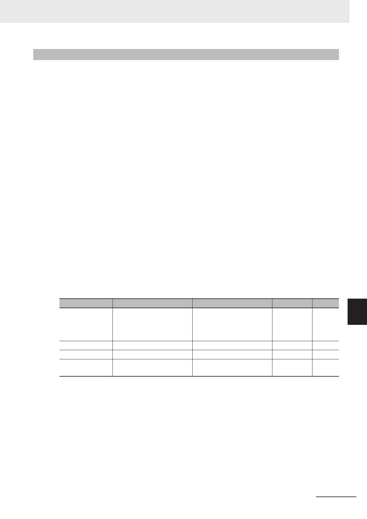
Parameter No. Function name Data Default data Unit
3005Hex-02Hex to
3005Hex-06Hex,
3005Hex-63Hex,
3005Hex-64Hex
Input Terminal [DI1] to [DI7]
Function Selection
47: LOCK (Servo lock com-
mand)
- -
300EHex-62Hex Servo Lock Gain 0.000 to 9.999 0.010 Time
300EHex-63Hex Servo Lock Completion Timer 0.000 to 1.000 0.1 s
300EHex-64Hex
Servo Lock Completion
Range
0 to 9999 10 Pulse
• When the servo lock command is ON, the voltage is output to the output terminals [U], [V] and [W] of
the inverter even if the RUN command has not been turned ON.
• During a servo lock, if the position error becomes four rotations or more by motor shaft conversion,
the position control error (alarm code: 38) is output.
•
With the servo lock function, as control is started from the 1st Stop Frequency (3004Hex-1AHex) or
less, adjust 1st Stop Frequency (3004Hex-1AHex) and Gain (300EHex-62Hex) to satisfy the follow-
ing formula:
1st Stop Frequency (3004Hex-1AHex) < (4 × Gain (300EHex-62Hex) × Maximum output frequency)
• If servo lock control is enabled, the stop frequency continuation operation and rotational direction
limitation are disabled.
8 Other Functions
8-133
M1 Series EtherCAT Type User’s Manual (I670)
8-9 Other Operation Functions
8
8-9-19 Servo Lock Function