A-2-4
Communication Objects
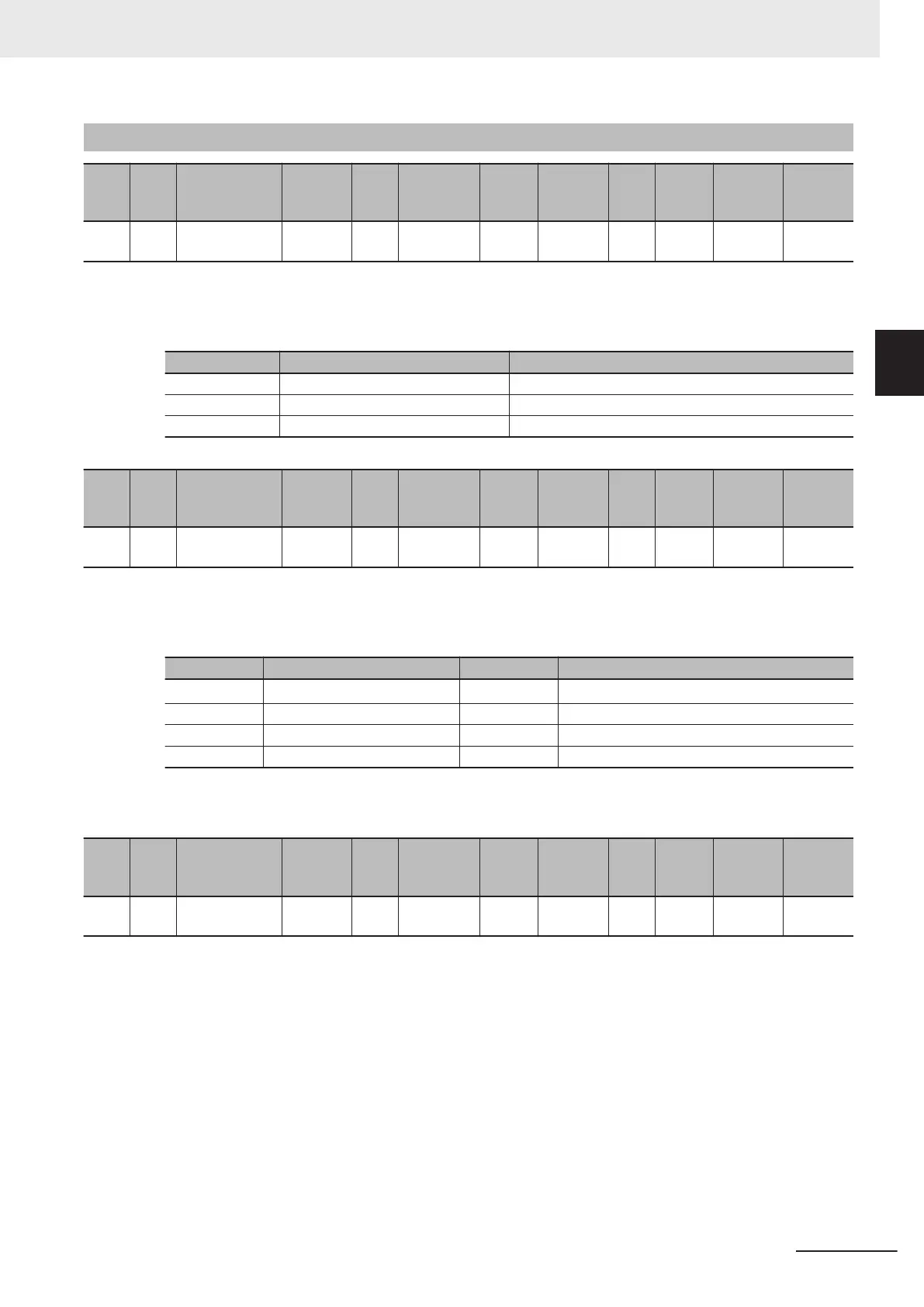
Index
(hex)
Sub-
index
(hex)
Object name
Setting
range
Unit
Default set-
ting
Data
attrib-
ute
Size
Ac-
cess
PDO
map
Complete
access
Modes of
operation
1000 --- Device Type --- --- 00090192
hex
--- 4 bytes
(U32)
RO --- Not possi-
ble
---
• Gives the CoE device profile number.
• Description of Set Values
Bit Name Description
0 to 15 Device profile number 402 (192 hex): Drive Profile
16 to 23 Type 09: FSoE general-purpose inverter
25 to 31 Mode 0: Manufacturer specific
Index
(hex)
Sub-
index
(hex)
Object name
Setting
range
Unit
Default set-
ting
Data
attrib-
ute
Size
Ac-
cess
PDO
map
Complete
access
Modes of
operation
1001 --- Error Register --- --- 0 --- 1 byte
(U8)
RO --- Not possi-
ble
---
• Gives the error type that has occurred in the inverter.
• Description of Set Values
Bit Description Bit Description
0 Generic error 4
Communication error (unsupported)
*1
1 Current error (unsupported) 5 Device profile specific error (unsupported)
2 Voltage error (unsupported) 6 Reserved
3 Temperature error (unsupported) 7 Manufacturer specific error (unsupported)
*1. In M1-series Inverters, bit 0 turns ON when an alarm occurs. It does not turn ON for a light alarm or EtherCAT commu-
nication error.
Index
(hex)
Sub-
index
(hex)
Object name
Setting
range
Unit
Default set-
ting
Data
attrib-
ute
Size
Ac-
cess
PDO
map
Complete
access
Modes of
operation
1008 --- Manufacturer
Device Name
--- ---
*1
--- 20 bytes
(VS)
RO --- Not possi-
ble
---
*1. The following table shows the default settings. It gives the inverter models.
Appendices
A-9
M1 Series EtherCAT Type User’s Manual (I670)
A-2 CoE Objects
A
A-2-4 Communication Objects