SII
(1)
(2)
(3)
(4)
(5)
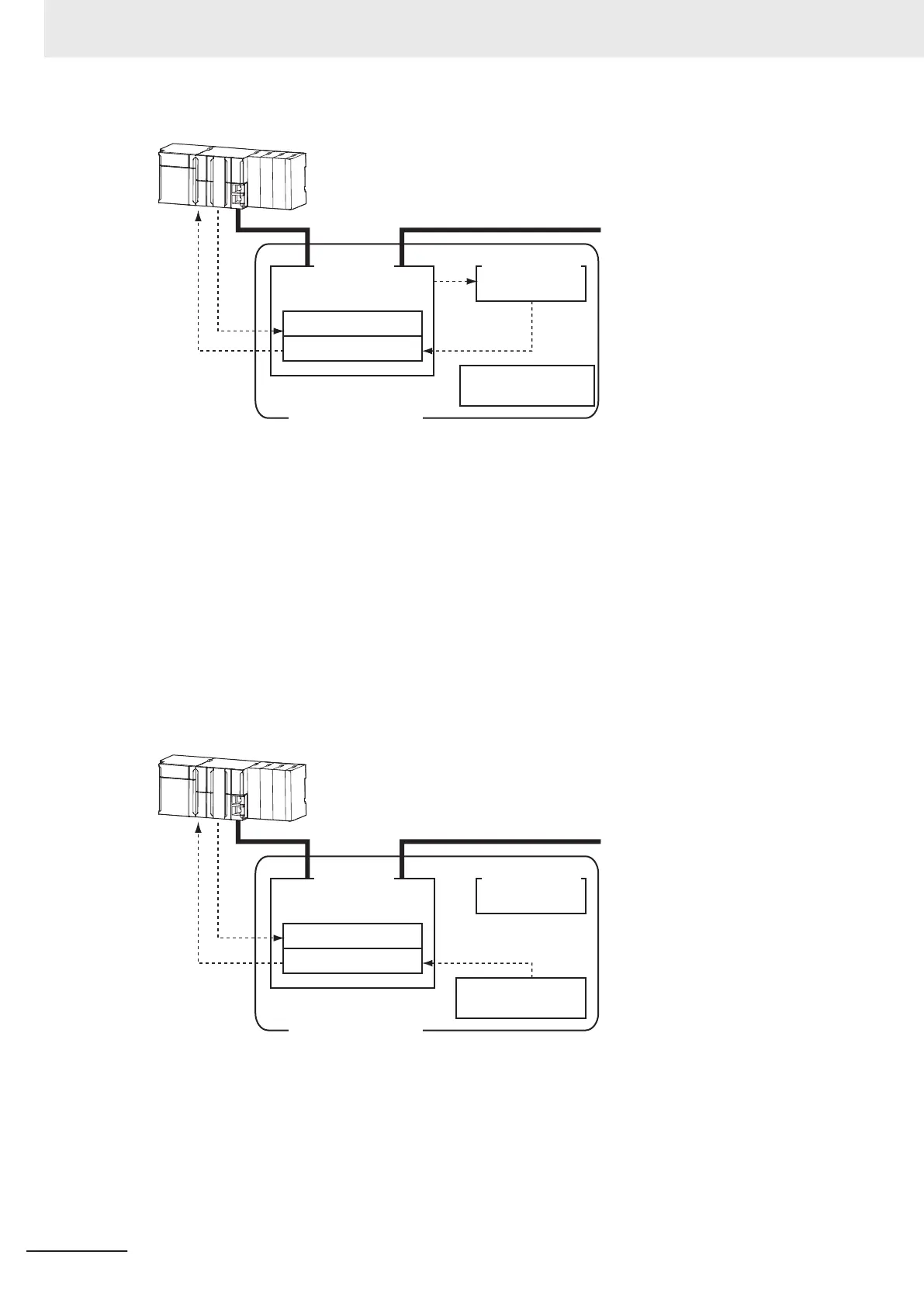
EtherCAT Master
EtherCAT
Slave Controller
Non-volatile
memory
Register: 0010 hex
Register: 0012 hex
EtherCAT Slave
(Inverter)
ID switches
1. Set the ID switches to 00 during power OFF.
2. Write a node address value to Slave SII from the master.
3. When the slave power is turned ON, the node address value is applied to Register: 0012 hex by
the software.
4. The EtherCAT master reads the value that is set in Register: 0012 hex.
5. The EtherCAT master writes the value of 0012 hex to 0010 hex of the EtherCAT slave as the
node address.
Switch Setting
The value of the ID switches of the slave is used as the node address.
SII
(1)
(2)
(3)
(4)
ID switches
EtherCAT Slave
(Inverter)
Non-volatile
memory
EtherCAT
Slave Controller
Register: 0010 hex
Register: 0012 hex
EtherCAT Master
1. Set the ID switches during power OFF.
2. When the slave power is turned ON, the value of the ID switches is applied to the register: 0012
hex.
3. The EtherCAT master reads the value that is set in Register: 0012 hex.
4. The EtherCAT master writes the value of 0012 hex to 0010 hex as the node address.
3 EtherCAT Communications
3-14
M1 Series EtherCAT Type User’s Manual (I670)