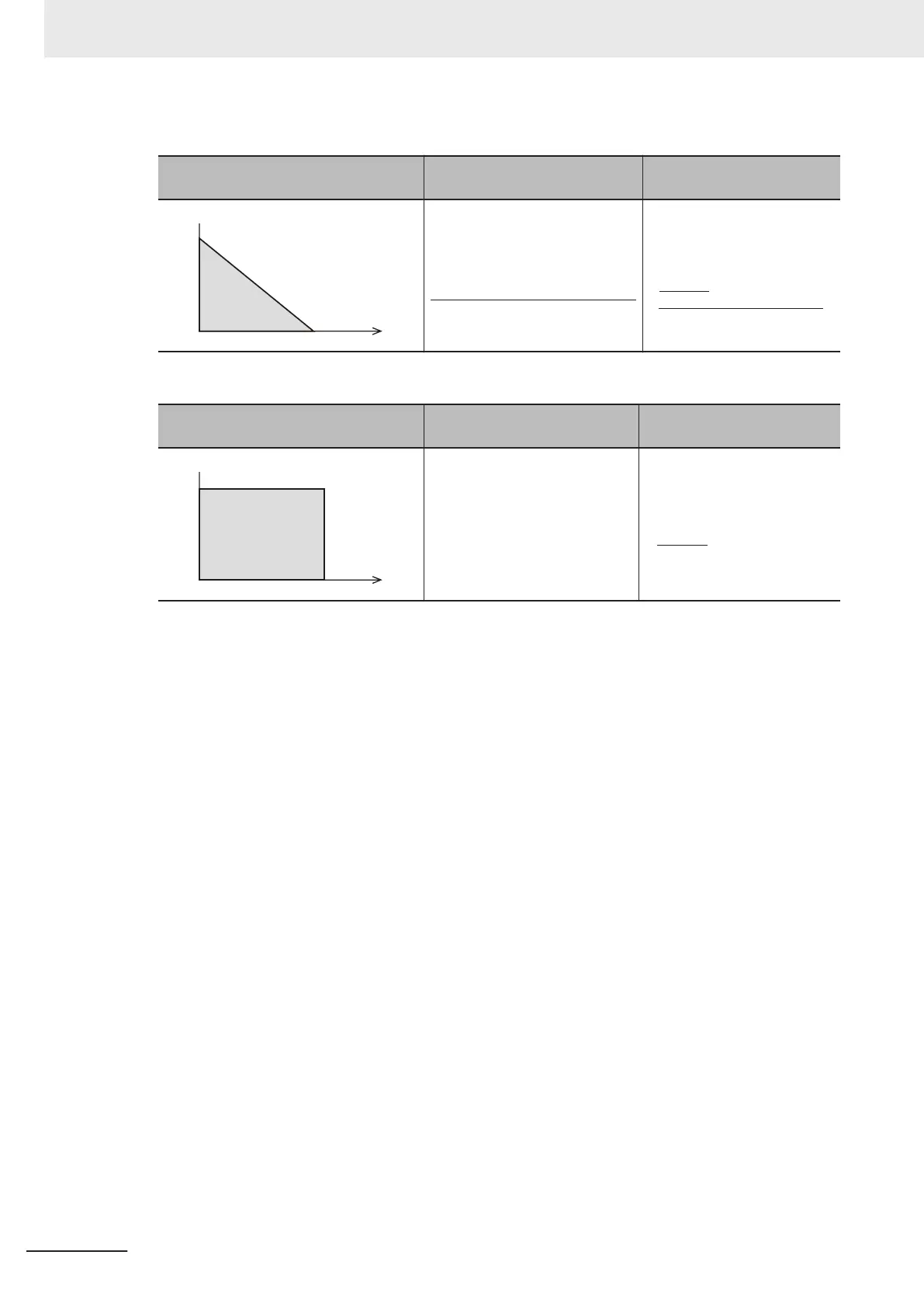
When braking load during deceleration decreases with time
How to apply a braking load Allowable average loss
Thermal braking resistance
value
Electronic Thermal for Braking
Resistor Discharging Capacity
(3004Hex-33Hex) =
Braking time (s) × Motor capacity (kW)
2
Electronic Thermal for Braking
Resistor Allowable Avera
ge
Loss (3004Hex-34Hex) =
× Motor capacity (kW)
2
%ED(%)
*1
100
When braking load at deceleration is a constant speed
How to apply a braking load Allowable average loss
Thermal braking resistance
value
Braking time (s) × Motor capacity (kW)
Electronic Thermal for
Braking
Resistor Discharging Capacity
(3004Hex-33Hex) =
× Motor capacity (kW)
%ED(%)
*
1
100
Electronic Thermal for Braking
Resistor Allowable Average
Loss (3004Hex-34Hex) =
*1. %ED indicates the usage rate. It is the percentage of the time under braking in the interval where the
brake is applied. (Reference: A-10-3 Overview of Braking Resistor Selection on page
A-299)
• When a braking resistor capable of outputting a temperature detection signal is applied, allocate
“9: EXT (external trip)” to one of input terminals [DI1] to [DI7], and connect the temperature de-
tection signal of the braking resistor.
•
Even if there is actually little temperature rise, the electronic thermal sometimes is activated and
the overheating protection (alarm code: 16 hex) is generated depending on the braking resistor
specifications. Check the specifications of the braking resistor and set its parameter.
6 Basic Settings
6-68
M1 Series EtherCAT Type User’s Manual (I670)