Even if an analog input is unipolar, the frequency setting can be set as bipolar by setting bias as a
negative value.
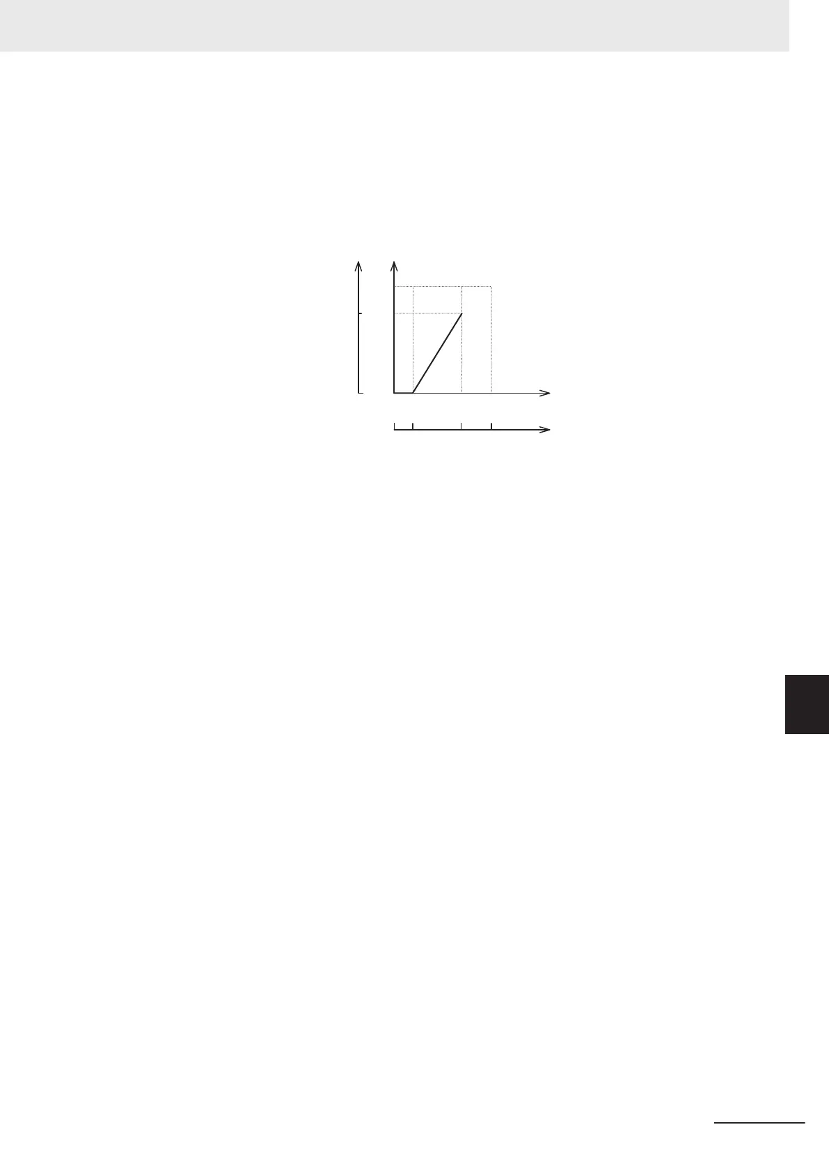
Example) When setting the set frequency 0 to 60 Hz by analog input AI1 1 to 5 V (1st Maximum Out-
put Frequency (3004Hex-04Hex) = 60 Hz)
(Converted with 1st Maximum Output Frequency
(3004Hex-04Hex) = 60 Hz taken as 100%)
Input Terminal [AI1] Gain
(Command) (3006Hex-21Hex)
Input Terminal [AI1] Bias for 1st
Frequency Command
(3004Hex-13Hex)
Input Terminal
[AI1] Bias Analog
Input for 1st
Frequency
Command
(3006Hex-33Hex)
Input Terminal
[AI1] Gain
(Analog Input)
(3006Hex-23H
ex)
Set frequency
Analog input (voltage)
Analog input (%)
(Analog input full scale:
Converted with 10 V taken as 100%)
Hz %
60Hz 100%
0
0Hz
100%50%10%
1V 5V 10V
B point
A point
(A point)
To take the frequency reference to be 0 Hz when the analog input is 1 V, set Input T
erminal [AI1] Bias
for 1st Frequency Command (3004Hex-13Hex) to 0%. At this time, as 1 V becomes the bias base
point and 1 V is equivalent to 10% of full scale 10 V of terminal AI1, set Input Terminal [AI1, AI2] Bias
Analog Input for 1st Frequency Command (3006Hex-33Hex) to 10%.
(B point)
To take the frequency reference to be the maximum frequency when the analog input is 5 V, set Input
Terminal [AI1] Gain (Command) (3006Hex-21Hex) to 100%. At this time, as 5 V becomes the gain
base point and 5 V is equivalent to 50% of full scale 10 V of input terminal [AI1], set Input Terminal
[AI1] Gain (Analog Input) (3006Hex-23Hex) to 50%.
Input terminal [AI1] can be used with bipolar inputs (-10 V to 10 V) by setting Input Terminal [AI1] Po-
larity Selection (3006Hex-24Hex) to “0.”
When Input Terminal [AI1] Bias for 1st Frequency Command (3004Hex-13Hex) and Input Terminal
[AI1] Bias Analog Input for 1st Frequency Command (3006Hex-33Hex) are both set to “0,” the com-
mand becomes symmetrically inverted as shown in the figure below.
8 Other Functions
8-37
M1 Series EtherCAT Type User’s Manual (I670)
8-3 Analog I/O Settings
8
8-3-2 Analog Input Adjustment Function
 Loading...


