Perform wiring with reference to the wiring example to meet the applicable safety standards. Be sure
to use both the safety input [SF1] and [SF2] terminals and configure a system that turns OFF both of
the [SF1] and [SF2] terminals when the safety function is activated.
If the inverter detects that either the [SF1] or [SF2] terminal is OFF, the safety function is activated and
the inverter shuts of
f the output.
• The STO (Safe Torque Off) Performance Monitor (102: EDM) turns ON when the inverter detects
that both of the [SF1] and [SF2] terminal signals turn OFF and shuts off the output. If the EDM out-
put does not turn ON even when the inverter shuts off the output by the safety function, check the
[SF1] and [SF2] terminal input circuits and the EDM detection circuit.
• The EN circuit failure detected (101: DECF) turns ON when an error occurs in the circuit that detects
that the SF terminal is OFF.
Parameter No. Function name Data
Default da-
ta
Unit
3005Hex-15Hex/
3005Hex-1CHex
Output Terminal [DO1] Function
Selection/Output Terminal
[ROA, ROB] Function Selection
101: DECF (EN circuit fail-
ure detected)
102: EDM (STO (Safe T
or-
que Off) Performance Mon-
itor)
- -
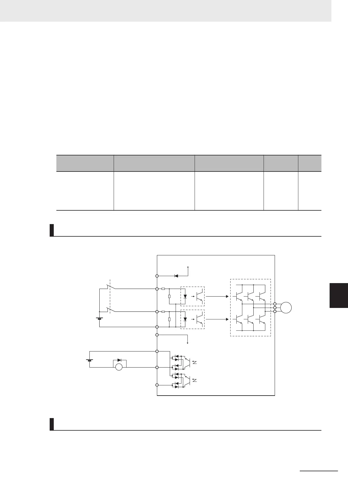
Wiring Example
Wiring example when EDM is enabled (for compliance with ISO13849-1 PL-e)
+24V
SF2
SF1
DIC
DOC
DO1
DO2
X
M
24V
EDM
3G3M1
System Configuration Example
To attain CAT.3, PL e/SIL3 as an overall system that uses the 3G3M1 Series, a PL e/SIL3 device must
at least be combined into the system.
8 Other Functions
8-63
M1 Series EtherCAT Type User’s Manual (I670)
8-6 Safety Function
8
8-6-3 STO Function by Safety Input Signal
 Loading...


