• If the L/A IN and L/A OUT indicators are OFF, the ring disconnection status has not been
fixed yet. Move on to the next step.
3 Replace the relevant cable with a new EtherCAT communications cable.
• Replace the EtherCA
T communications cable between "Inverter A" and "Inverter B" with a
new cable. To avoid incorrect wiring, do not remove any other cable.
• If the L/A OUT indicator of "Inverter A" and the L/A IN indicator of "Inverter B" are ON or
flashing, the ring disconnection status has been resolved.
• If the L/A IN and L/A OUT indicators are OFF, Inverter A or B is faulty. Move on to the next
step.
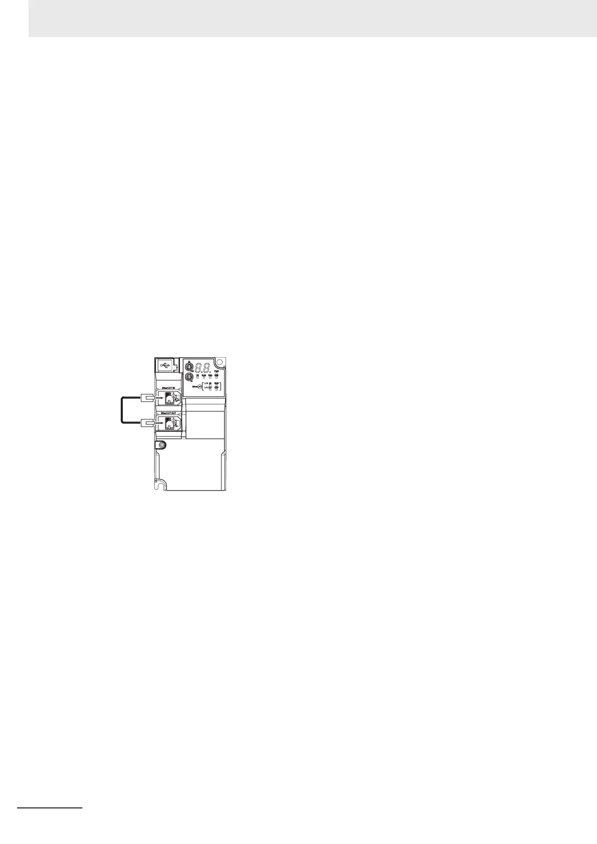
4 Identify a faulty inverter.
• As in the following figure, connect one EtherCA
T communications cable to the ECAT IN and
ECAT OUT connectors on "Inverter A". If the L/A IN and L/A OUT indicators remain OFF,
"Inverter A" is faulty.
• In the same way, connect one EtherCAT communications cable to the ECAT IN and ECAT
OUT connectors on "Inverter B". If the L/A IN and L/A OUT indicators remain OFF, "Inverter
B" is faulty.
5 Replace the identified faulty inverter.
• T
urn OFF the power supply, and replace the inverter.
6 Turn ON the power supply to the devices, and then establish EtherCAT communications.
• Connect the EtherCA
T communications cables correctly, and turn ON the power supply to
the EtherCAT master and to the slaves.
10 Maintenance and Inspection
10-10
M1 Series EtherCAT Type User’s Manual (I670)
 Loading...


