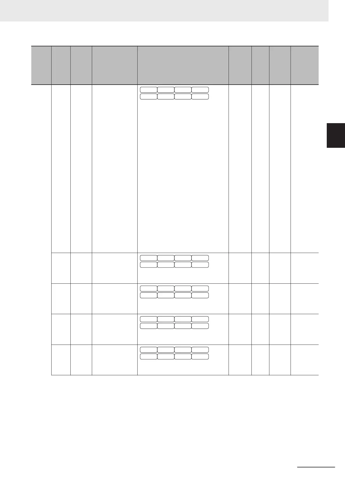
Index
(hex)
Sub-
index
(hex)
Pa-
rame-
ter No.
Function name Monitor or data range
Default
data
Set-
ting
dur-
ing
RUN
Unit
PDO
map
1E W29 Frequency and
PID Command
Source Monitor
V/f DTV
PG V/f PG DTV
SLV PGV
PM SLV PM PGV
1: Analog Voltage Input (Input Termi-
nal[AI1])
7: UP/DOWN control
10: Pattern operation
13: Pulse train input or Frequency
calculation
22: EtherCAT
23: Support Tool
24: Multi-step Frequency
25: Jogging Frequency
30: PID Control Operator Process
31: PID Control Analog Process
33: PID Control UP/DOWN control
34: PID Control Communication
Process
36: PID Control Multi-Step Terminal
Process
255: Not Selected
Others: Reserved
0 --- --- Possible
(TxPDO)
1F W30 Speed in Per-
centage
V/f DTV
PG V/f PG DTV
SLV PGV
PM SLV PM PGV
0.00 to 100.00
0 --- % Possible
(TxPDO)
20 W31 Speed Set Value
in Percentage
V/f DTV
PG V/f PG DTV
SLV PGV
PM SLV PM PGV
0.00 to 100.00
0 --- % Possible
(TxPDO)
21 W32 PID Output Moni-
tor
V/f DTV
PG V/f PG DTV
SLV PGV
PM SLV PM PGV
-150.00 to 150.00
0 --- % Possible
(TxPDO)
22 W33 Analog Input
Monitor
V/f DTV
PG V/f PG DTV
SLV PGV
PM SLV PM PGV
-9,990 to 9,990
0 --- --- Possible
(TxPDO)
Appendices
A-67
M1 Series EtherCAT Type User’s Manual (I670)
A-4 Lists of Manufacturer Specific Objects 2
(Inverter Parameters)
A
A-4-2 W Group Parameter List (Monitor 2)
 Loading...


