A
Appendix
A-4 CP1L Programming Examples
SYSMAC CP1L/CP1E Introduction Manual 129
■System Configuration
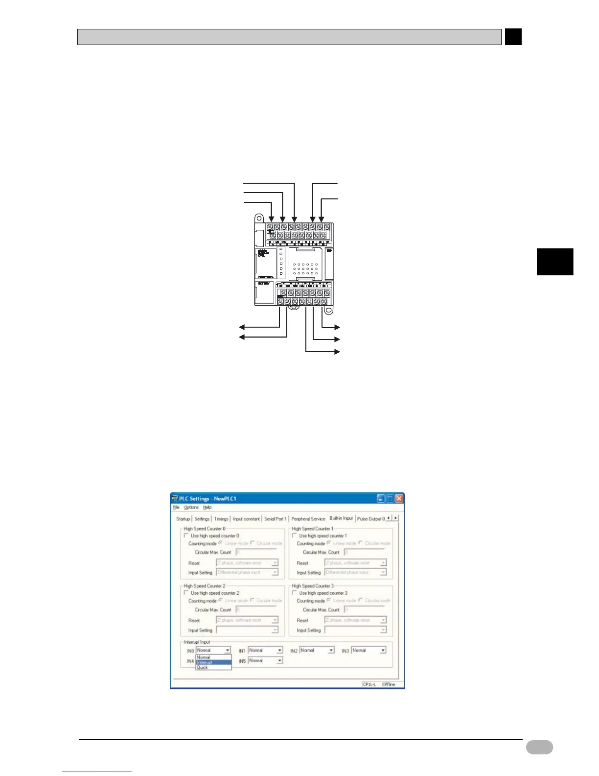
●Wiring Example
On CP1L units with 14-point I/O, interrupt inputs can be allocated to contacts 0.04
to 0.07.
Input interrupt 0 (CP1E: 4) will be allocated to contact 0.04. The interrupt task
executed by input interrupt 0 (CP1E: 4) is task No.140 (CP1E: No.4).
●PLC Setup
Set contact 0.04 to be [Interrupt].
1. Open the PLC Settings dialog box.
2. Click the Built-in Input tab.
3.
On the IN0 (CP1E: IN4) drop-down list for [Interrupt Input], select [Interrupt].
While the sensor input contact is 0.04, setup is performed for [IN0 (CP1E:
IN 4)] since the interrupt input setting is set to 0 (CP1E: 4).
4. Close the PLC Settings dialog box.
5. To apply changes made to the PLC settings, turn the PLC power ON.
PASS output 100.00
NG output 100.01
NG output sensor input 1 100.02
NG output sensor input 2 100.03
NG output sensor input 3 100.04
Sensor input (interrupt input 0) 0.04
RESET input 0.05
CP1L