A
Appendix
A-4 CP1L Programming Examples
146 SYSMAC CP1L/CP1E Introduction Manual
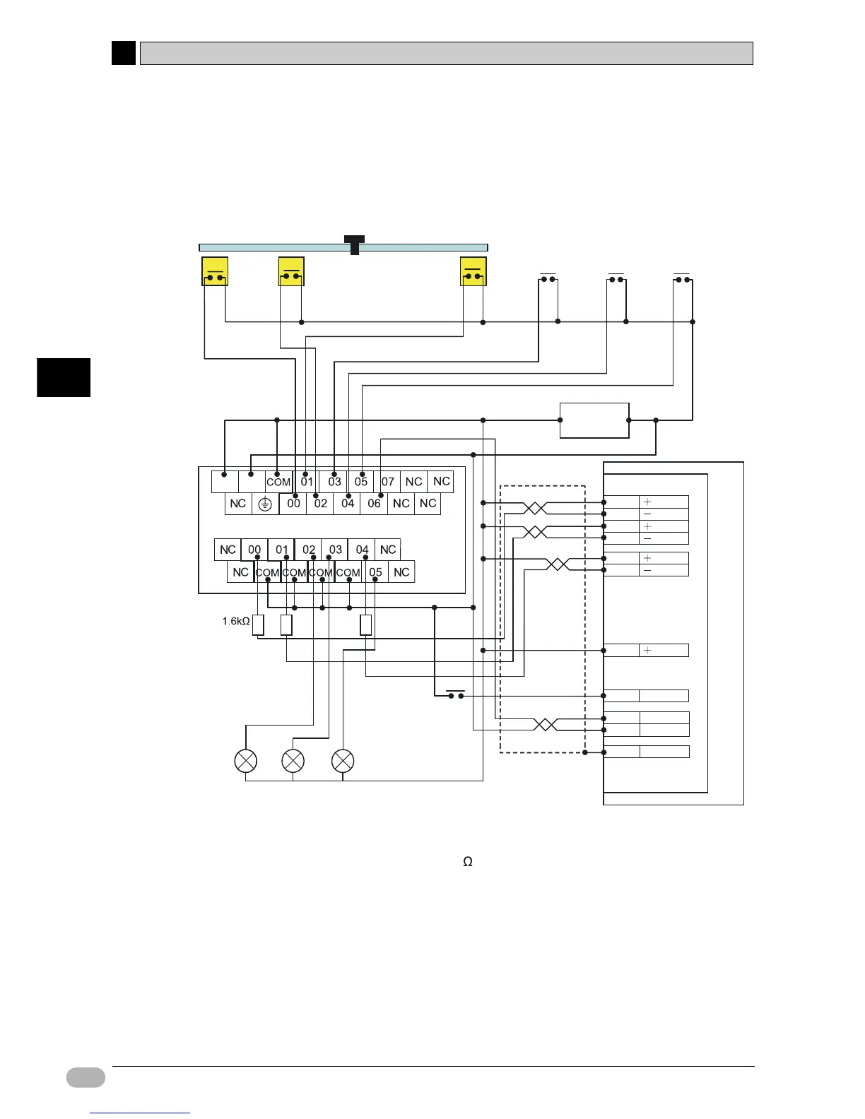
■System Configuration
●Wiring Example
*1 Insert a resistance of 1.6 to 2.2k , so that the current is within the 7 to 15mA
range.
*2 The bit allocations of origin proximity sensor, origin input and error counter reset
output are different with the CPU unit I/O points. Refer to CP Series CP1E CPU
Unit User's Manual (W462) or CP Series CP1E CPU Unit Hardware User's
Manual (W479) for the details on allocation.
*3 For CP1E units, the pulse will be set to 100.00 and the direction will be set to
100.01. Set the servo drive to pulse plus direction.
CCW limit
Senser (E2E-series)
sensor
0.00
Origin proximity
sensor
0.02*
2
Start
origin search
0.03
24VDC
(S8VM-series)
+
Positioning
to point A
0.04 0.05
(*1)
CW
output
100.00*
3
CCW
outpput
100.01*
3
Error counter
reset output
100.04*
2
NO
contact
Origin search
complete
100.05
Point A
positioning
complete
100.02 100.03
1
CW
2
CW
3
CCW
4
CCW
5
ECRST
6
ECRST
13
24V IN
14
32
33
FG
CN1
NO
contact
NO
contact
CW limit
sensor
0.01
Positioning
to point B
-
Point B
positioning
complete
RUN
Z
ZCOM
R7D AP series
CP1L-L14DT
(*1)
(*1)
Indicator
(M16-series)
+
-
Hood
Switch (A16-series)
Origin input 0.06*
2