81
Wiring Methods Section 2-4
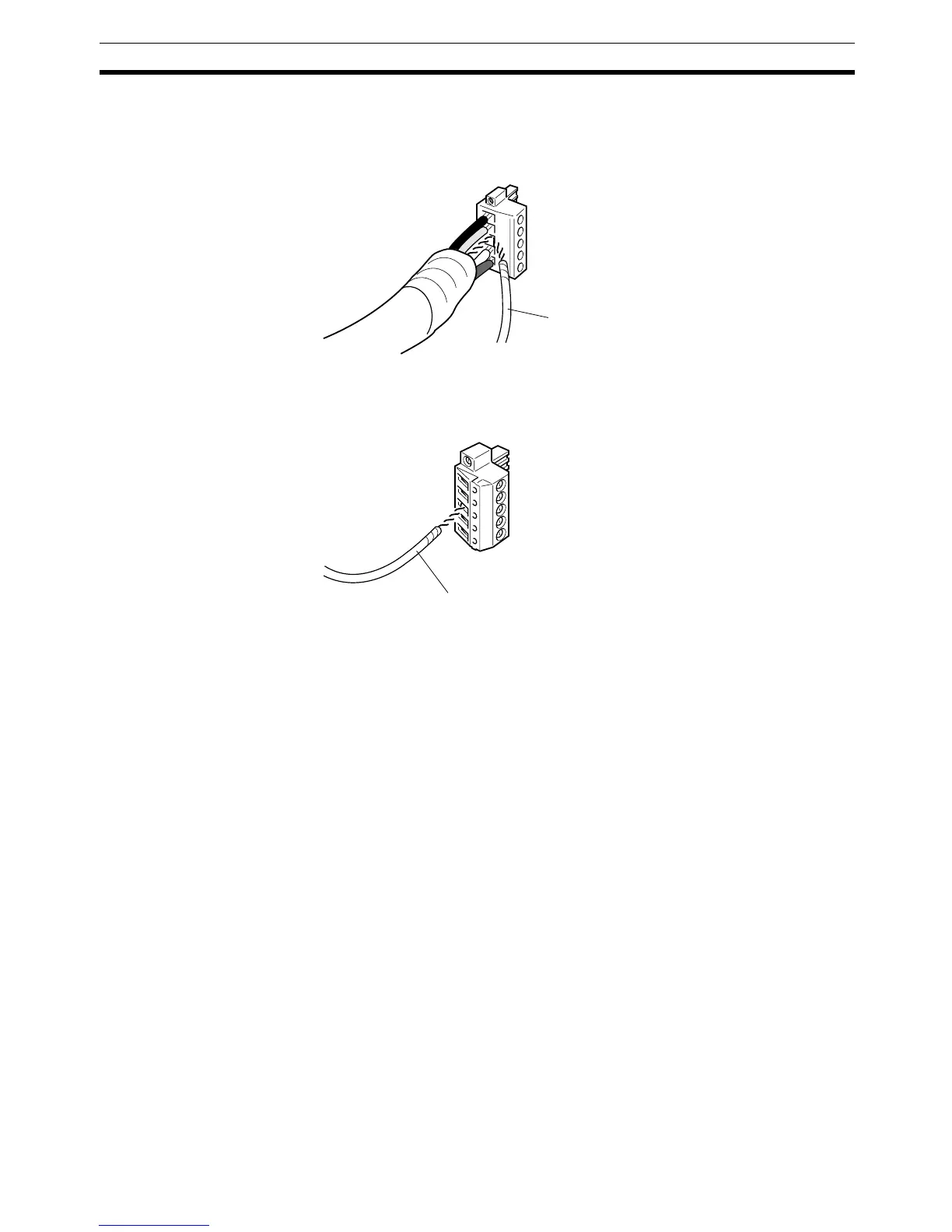
Grounding a T-branch Tap or Node Connector
The ground wire can be inserted into the connector together with the commu-
nications cable’s shield wire and both locked in place with the set screw, as
shown in the following diagram.
Grounding an Unused T-branch Tap Connector
The ground wire alone can be inserted in the connector of an unused T-
branch Tap connector, as shown in the following diagram.
Note 1. A ground of 100
Ω max. is recommended.
2. When an acceptable ground of 100 Ω max. is available, connect the com-
munications power supply’s V- and FG terminals.
3. When an acceptable ground of 100
Ω max. is not available, do not connect
the communications power supply’s V- and FG terminals. In this case, con-
necting the V- and FG terminals may introduce noise into the network.
Ground wire
Ground wire