39
Network Configuration Section 2-2
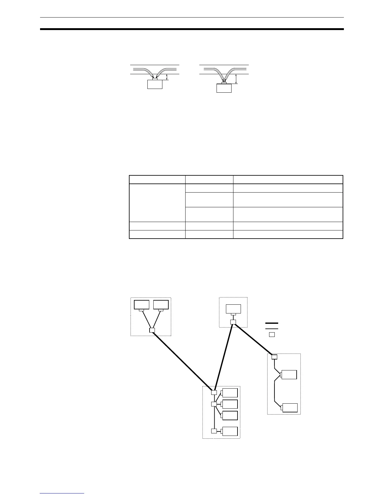
Proper Distance between
Wiring Duct and Node
Allow about 10 cm between the wiring duct and nodes so that the nodes can
be wired without straining the connectors. Communications errors may occur
if there isn’t enough slack in the cable and the connectors are pulled out.
Note Do not strip too much insulation and shielding from the cable. Removing too
much shielding will provide a path for noise to enter the network.
Considerations in
Choosing Special Thin/
Thick Cable or Special Flat
Cable
Using Special Flat Cable makes it easy to extend a branch cable using one-
touch connectors, but Special Flat Cable cannot be combined with a trunk line
consisting of Special Thin/Thick Cable. There are differences between Spe-
cial Thin/Thick Cable and Special Flat Cable in terms of maximum network
length, branch line length, and current capacity. For detailed specifications,
refer to 2-2-2 Trunk Lines and Branch Lines.
2-2-4 Determining the Location of the Master
It is not necessary to locate the Master at the end of the network. The Master
can be located at any node position on the trunk line or a branch line.
Configure the network as desired, since there is no restriction on the Master’s
location.
Duct
Incorrect Correct
Duct
Node
Node
Too close
Allow about 10 cm.
Trunk line Branch line Application
Flat cable Thick cable Connect to T-branch Tap.
Thin cable Connect using T-branch Connector
(DCN4-TR4-1 + DCN4-BR4D).
Flat cable Connect using T-branch Connector
(DCN4-TR4-1 + DCN4-BR4).
Thick cable Flat cable Connect to T-branch Tap.
Thin cable Flat cable Connect to T-branch Tap.
PLC Master
Trunk line
Branch line
T-branch Tap
Branch
lines
Branch
line
Main control panelSub-panel
Sub-panel
Sub-panel
Branch
lines