101
Step 3: Splitting the System into Multiple Power Supplies Section 3-6
3-6 Step 3: Splitting the System into Multiple Power Supplies
If the calculations in step 2 indicate that a single power supply cannot provide
power properly for the network, proceed with this step and install multiple
power supplies to split up the power supply system.
3-6-1 Splitting the Power Supply System
• When there are two or more power supplies in the network, Power Supply
Taps must be used to connect the power supplies.
• Remove a fuse in the Power Supply Tap to supply power to just one side
and split the power supply system.
Once the power supply system is split, return to Step 1 or 2, and evaluate
whether the separated power supply systems can supply power properly.
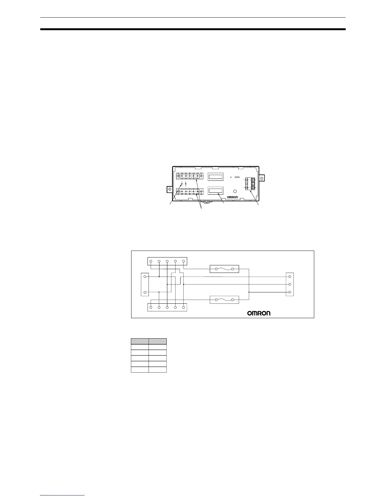
3-6-2 Configuration of the Power Supply Tap
3-6-3 Internal Circuits in the Power Supply Tap
Remove fuse F1 to cut off the power supply (V+) to CN1. Remove fuse F2 to
cut off the power supply (V+) to CN2.
Terminating Resistor
Socket (CN4)
Power Supply
Terminal Block (CN3)
Communications Cable
Connectors (CN1 and CN2)
Fuses (F1 and F2)
V−
L
S
H
V+
V−
CAN L
SHIELD
CAN H
V+
CN2
CN3
F2
F1
CN1
V−'L'S'
SV−V+
H'V+'
V+HSL
CN4
V
−
Pin Name