91
Locating the Power Supply Section 3-3
Note If the current carried by a thick cable exceeds 8 A even after the power supply
configuration has been changed, the power supply requirements cannot be
met with a single power supply and multiple power supplies must be used.
In configuration 1, the power can be supplied to the trunk line in both direc-
tions as long as the current in each direction is 8 A or less when using thick
cable. Consequently, it is possible to have a configuration with a total current
consumption up to 16 A. Change to thick cable if thin cable is being used in
the trunk line and the current through the thin cable exceeds 3 A.
3-3-2 Main Factors for Determining the Power Supply Location
Determine whether or not the current can be supplied normally by finding the
current capacity required by each node and the voltage drop in the cables to
be used to provide power. Calculate the values below in advance.
• The current required by each node
• The distance between the power supply and each node
3-3-3 Calculating the Power Supply Location
There are two methods to find the best location of the communications power
supply on the trunk line.
1. Simple estimation from a graph
2. Calculation by formula (Calculate the voltage drop based on the current re-
quirements of the nodes and the communications cable resistance.)
Each branch line must satisfy the equation on page 88, which shows the
maximum current capacity of a branch line based on its length.
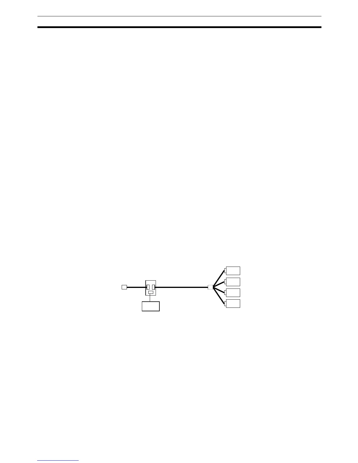
• The graph estimation assumes the worst case scenario from the
standpoint of the power supply (the configuration that has the maxi-
mum voltage drop as shown in the diagram below), so any actual pow-
er supply configuration will be acceptable based on the graph
estimation.
• Since the graph estimation assumes the worst case scenario, an actu-
al network configuration may be acceptable even if the configuration is
disallowed in the graph. Evaluate the configuration accurately by the
performing the calculations described in 3-5 Step 2: Evaluating the
Configuration with Calculations.
Note When a single power supply is used to provide the communications power
supply and the internal circuit supply, use the formula method to evaluate a
hypothetical power supply location because it cannot be evaluated with the
graphs. Refer to Shared Communications and Internal Circuit Power Supply
on page 97 for details on this calculation.
Power Supply Tap
Power
Supply
Node
Node
Node
Node