90
Locating the Power Supply Section 3-3
3-3 Locating the Power Supply
3-3-1 Power Supply Layout Patterns
The power supply can be set up in the configurations shown below. In gen-
eral, select either configuration 1 or 2 (a single power supply configuration.)
Use configuration when power supply requirements cannot be met with con-
figuration 1 or 2. For more details on each configuration, refer to sections 3-4
Step 1: Evaluating the Configuration with Graphs through 3-6 Step 3: Splitting
the System into Multiple Power Supplies.
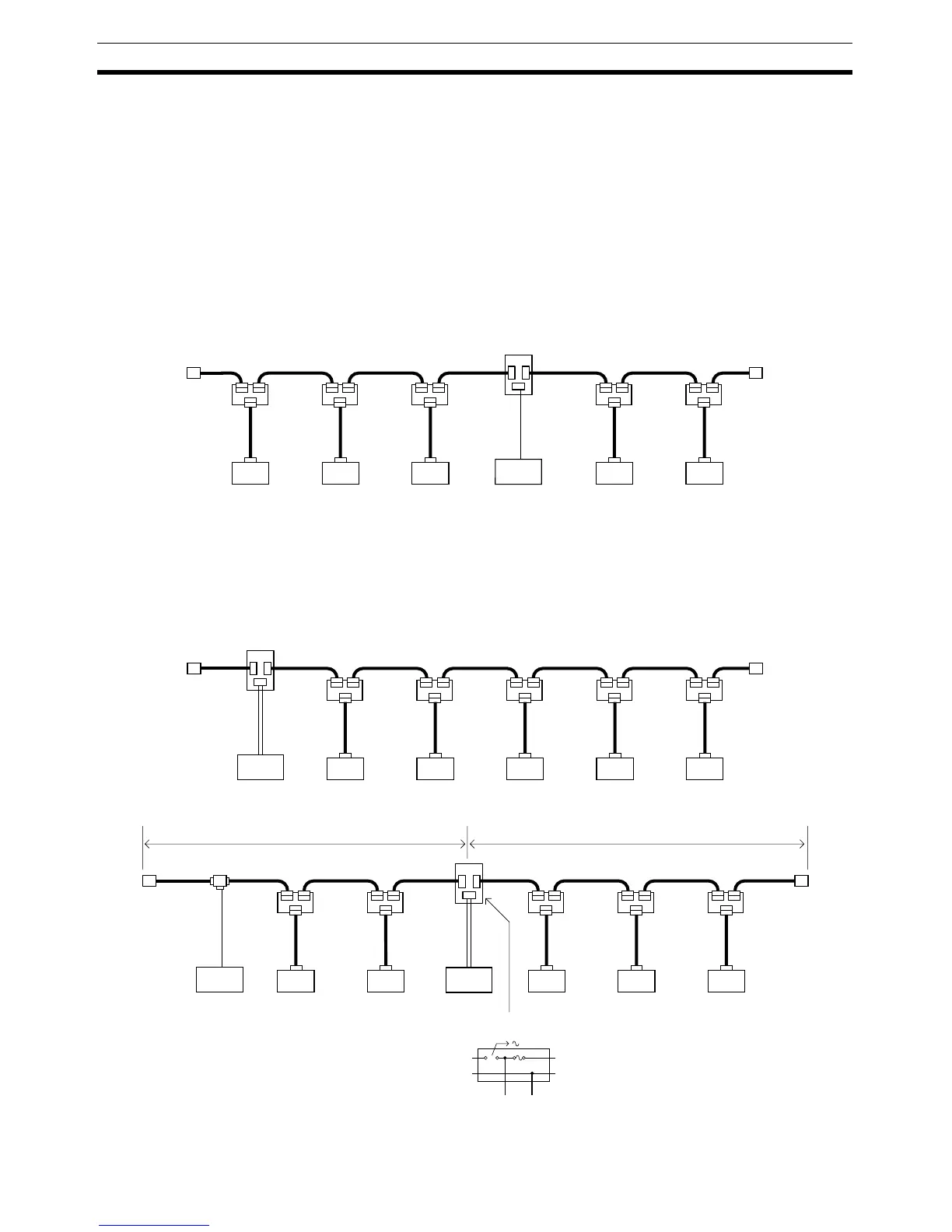
Configuration 1: Supplying Power to Nodes in Both Directions
Configuration 2: Supplying Power to Nodes in One Direction
Note (1) Configuration 1 is recommended when a single power supply is being
used to provide power to many nodes.
(2) When flat cable is used, power can be supplied from a DCN4-TP4D Flat
Cable Terminal Block with Terminating Resistance.
Configuration 3: Dividing the Power Supply System
Power Supply Tap
or T-branch Tap
Node Node Node NodeNode
Power
supply
Power Supply Tap
or T-branch Tap
NodeNode Node NodeNode
Power
supply
V+
V−
24 V 0 V
Power Supply Tap
NodeNode Node NodeNode
Power
supply
Power
supply
Power Supply Tap
System 1 System 2
The V
− line is shared
by systems 1 and 2.
Remove fuse to cut off
V+ in this direction.
Fuse