83
Minimizing Noise in the Network Section 2-5
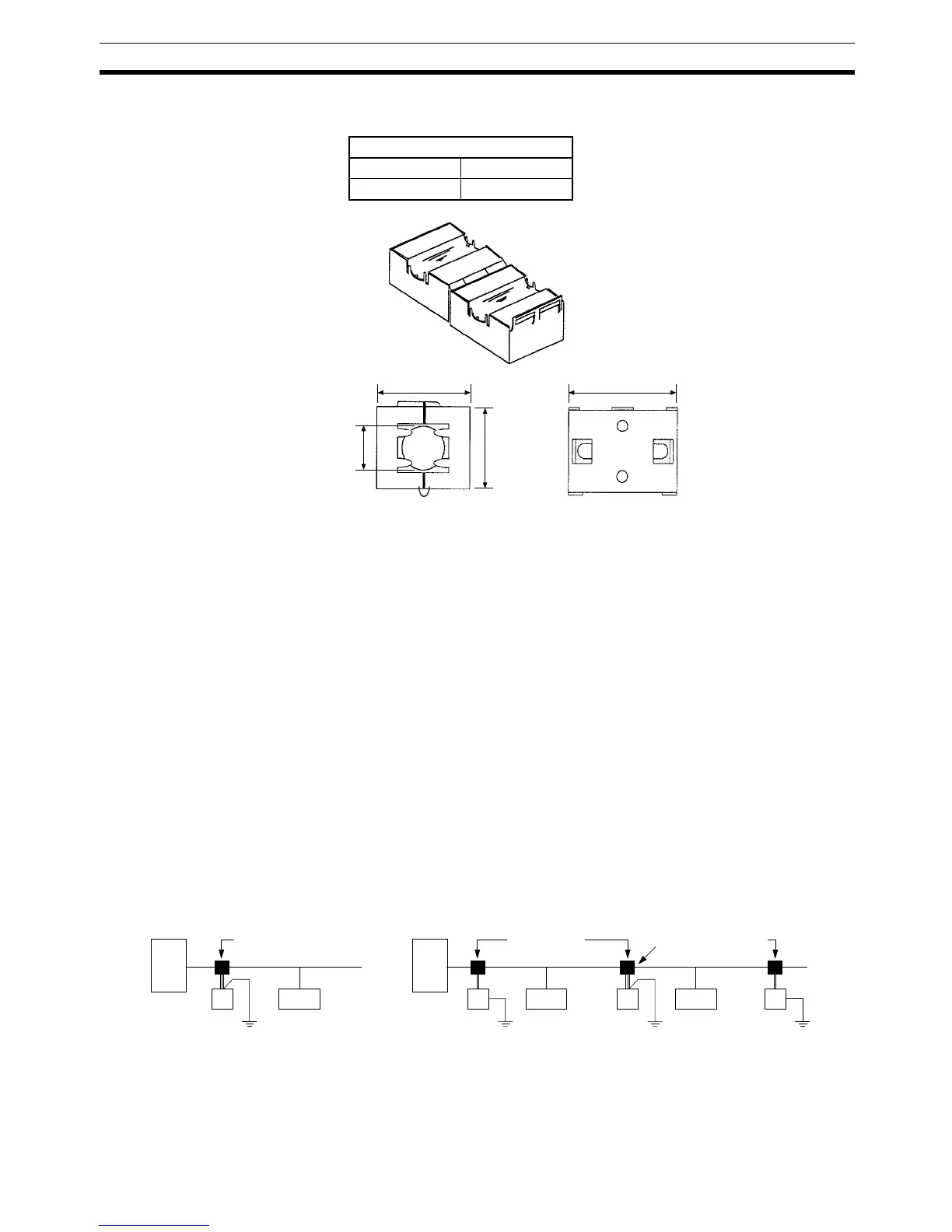
Ferrite Core (Data Line Filter):
Nisshin Electric Co, Ltd. model 0443-164151 or equivalent
• Since noise currents often flow through metallic equipment (such as cas-
ings), the communications cables should be placed as far away from
metallic equipment as possible.
• Ground the communications cable to 100
Ω max. with a ground wire that
is as short as possible.
• Ground the shielding wire on the communications cable at one point. If
the same ground is used for the communications cable and communica-
tions power supply, there is a possibility that noise may be transmitted
through the ground line to the communications line. In order to avoid this,
be sure that the power line ground and the grounds for the communica-
tions cables and the communications power supply are located as far
from each other as possible.
• Insert a line filter on the primary side of the communications power sup-
ply.
• When there are two or more communications power supplies, ground the
shielding wire at the Power Supply Tap near the center of the communica-
tions cable. Do not ground the shielding wire at more than one place.
(In the following diagram, “PS” indicates a communications power supply.)
Note Do not connect the Power Supply Tap’s shield (S) terminal to the communica-
tions power supply’s FG terminal at these two Power Supply Taps.
Inductance specifications
25 MHz 100 MHz
156 Ω 250 Ω
30 mm
29 mm
32 mm
13 mm
(See note.) (See note.)
Power Supply Tap,
T-branch Tap, or
T-branch Connector
Power
Supply Taps
Power
Supply Tap
Ground at
one point
Master
Slave
PSPS
Slave
PSPS
Slave
Master
Network with 1 Communications Power Supply Network with 2 or more Communications Power Supplies