46
Cables, Connectors, and Related Devices Section 2-3
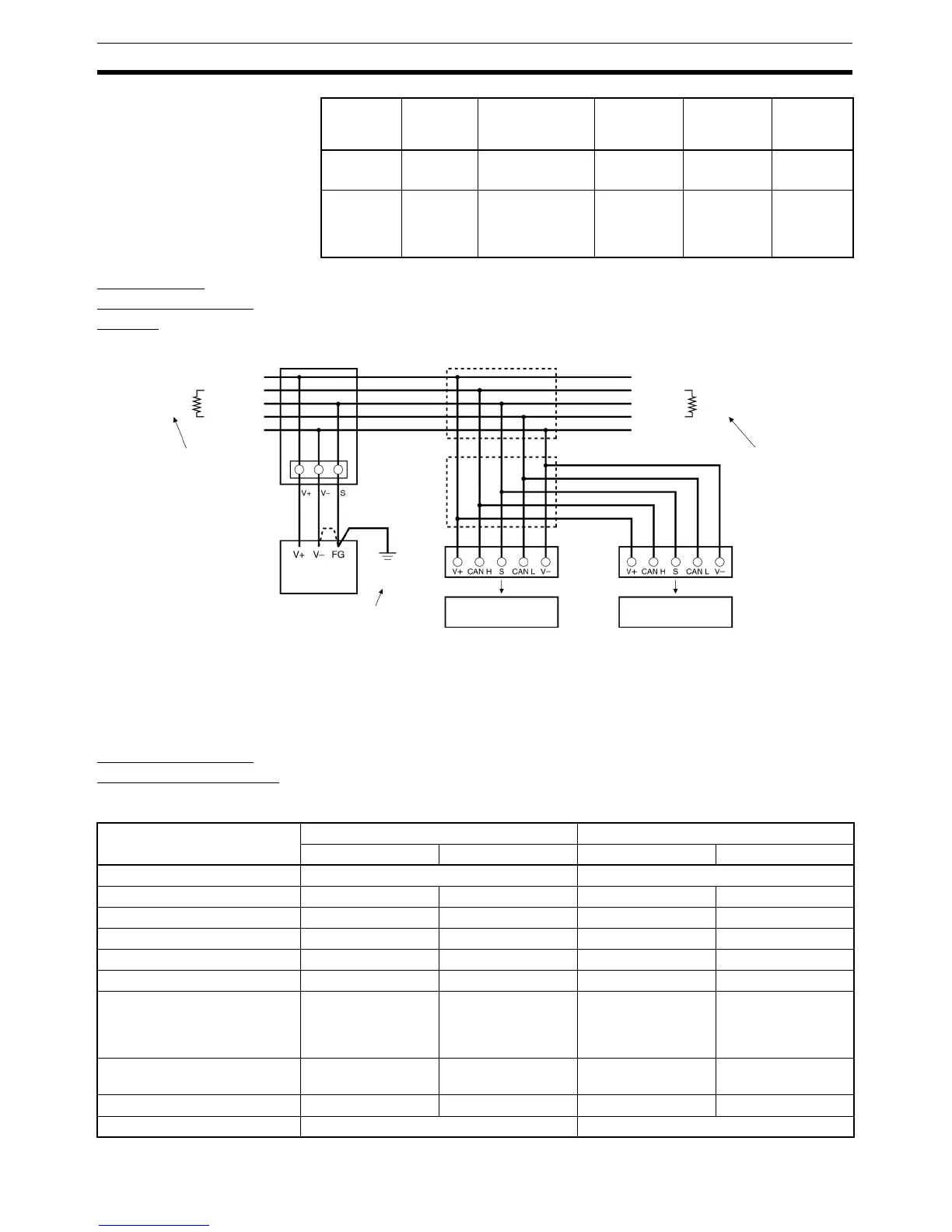
Connecting
Communications
Cables
Note The ground may introduce noise into the network if a poor quality ground is
used and the FG terminal is connected to the V- terminal. If a good ground of
100
Ω or less is not available, do not connect the communication power sup-
ply’s FG and V- terminals.
Communications
Cable Specifications
Special Thin/Thick Cable
3BlueCAN L
(signal low)
0.5 mm
2
(AWG21)
37.5 max. ---
4BlackV−
(communica-
tions power sup-
ply negative side)
0.75mm
2
(AWG19)
25.0 max. 5 max.
Conductor
No.
Insulation
color
Application Nominal
cross-
section
Conductor
resistance
(Ω/km)
Allowable
current (A)
Terminators are
required at both
ends of the network.
V+ (Red)
CAN H (White)
Shield
CAN L (Blue)
V- (Black)
V+ (Red)
CAN H (White)
Shield
CAN L (Blue)
V- (Black)
Terminating
Resistor
(121
Ω)
Terminating
Resistor
(121
Ω)
Terminators are
required at both
ends of the network.
Trunk line
Branch line
Node Node
T-branch Tap or
T-branch Connector
Power Supply Tap
T-branch Tap
or T-branch
Connector
Connec-
tor
Communications
Power Supply
(24 V DC)
Ground
(100
Ω or less)
Ground the network
at one point only.
Item Thick Cable Thin Cable
Signal wires Power wires Signal wires Power wires
Model DCA2-5C10 DCA1-5C10
Conductor cross-sectional area 0.86 mm
2
2.17 mm
2
0.20 mm
2
0.38 mm
2
Conductor outer diameter 1.21 mm 1.92 mm 0.60 mm 0.80 mm
Color Blue and white Red and black Blue and white Red and black
Impedance 120 Ω ±10% --- 120 Ω ±10% ---
Propagation delay 1.36 ns/ft --- 1.36 ns/ft ---
Attenuation factor 500 kHz: 0.25 dB/
100 ft
125 kHz: 0.13 dB/
100 ft
--- 500 kHz: 0.50 dB/
100 ft
125 kHz: 0.29 dB/
100 ft
---
Conductor resistance 6.9 Ω/1,000 ft
22.6 Ω/1,000 m
2.7 Ω/1,000 ft
8.9 Ω/1,000 m
28 Ω/1,000 ft
91.9 Ω/1,000 m
17.5 Ω/1,000 ft
57.4 Ω/1,000 m
Maximum current --- 8 A --- 3 A
Finished outer diameter 11.2 to 12.1 mm 6.9 mm