77
Wiring Methods Section 2-4
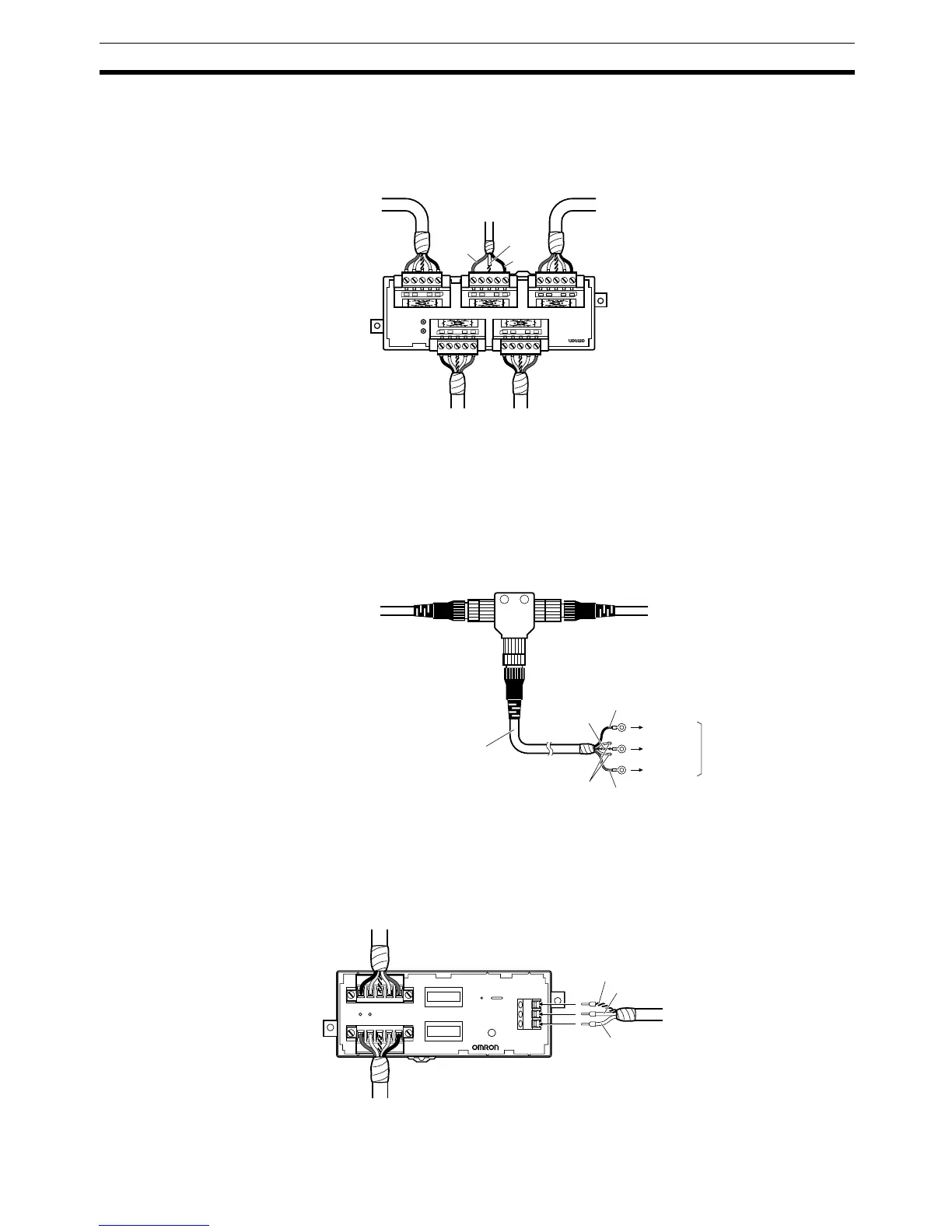
Connecting to a T-branch Tap
Insert the communications power supply lines (V+ and V− wires) to the con-
nector holes where the communications cable’s V+ (red) wire and V
− (black)
wire are normally connected, as shown in the following diagram.
Connecting to a T-branch Connector
Connect the communications power supply lines (V+ and V
− wires) to the V+
(red) wire and V
− (black) wire of a communications cable connected to the T-
branch Connector, as shown in the following diagram. This example shows a
DCN2-1 T-branch Connector, but the connection method is the same for other
T-branch Connectors.
Connecting to a DCN1-1P Power Supply Tap
Insert the communications power supply lines to the terminal block provided
for the communications power supply input, as shown in the following dia-
gram.
DCN1-3C
T-PORT TAP
V+
V−
Trunk line Trunk line
Branch
line
Branch
line
Shield
To communications
power supply
(24 V DC)
Red (V+)
Black (V
−)
Trunk line Trunk line
Cable with shielded connector
(male plug) on one end
T-branch Connector
Shield
wire
To V
−
To FG
To V+
Insulate the blue and
white signal wires.
Communications
power supply
(24 V DC)
V−
V+
Trunk line
Shield wire
To communications
power supply (24 V DC)
Trunk line