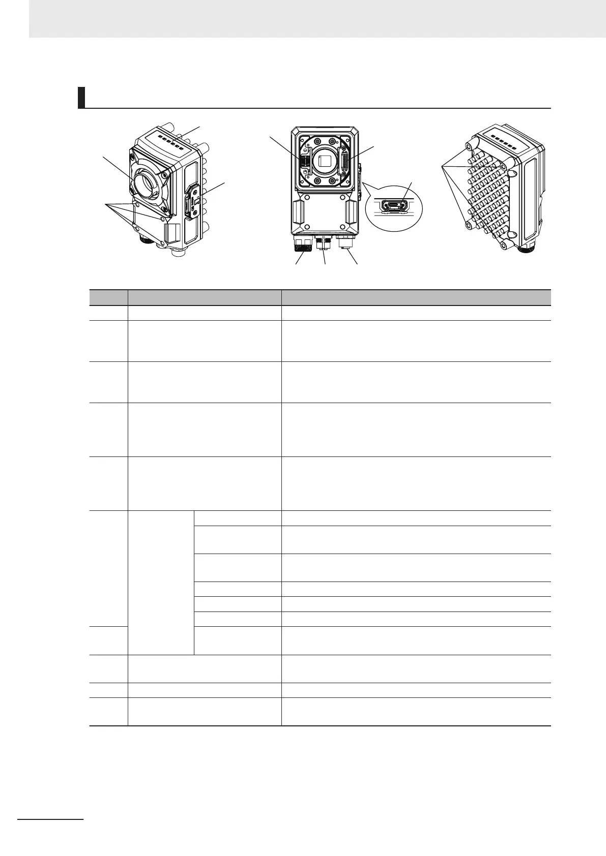
Component Names and Functions
No. Name Description
1 Imaging unit Captures images.
2 Connector for I/O cable Use this connector when connecting the smart camera with a
power supply or an external device using an I/O cable.
Dedicated I/O cable: FHV-VD
3 Connector for Ethernet cable Use this connector when connecting the smart camera with a
personal computer and so on using an Ethernet cable. Dedicat-
ed Ethernet cable: FHV-VN
4 Connector for external lighting Use this connector when connecting an external lighting and the
external lighting controller.
Connectable external lighting controller: FL-TCC and FLV-
TCC
5 Connector to attach microSD card Use this connector to attach a microSD card. Do not extract/
insert the microSD card during processing.
Otherwise, measurement time may be influenced or data may
be broken.
6 Operation
indicator
PWR (Green) Lights while power is supplied.
RUN (Green) Lights when switching to the layout in which the RUN signal out-
put is set ON.
LINK (Yellow) Lights when connected with Ethernet equipment and blinks dur-
ing communication.
BUSY (Green) Lights while processing is in progress.
OR (Yellow) Lights when the overall judgment output signal is ON.
ERR (Red) Lights when an error occurs.
7 SD ACCESS (Yel-
low)
Lights when accessing to the microSD card.
8 Connector for lighting module
(white)
Use this connector when mounting the lighting module.
9 Connector for lens module (Black) Use this connector when mounting the lens module.
10 Mounting screw holes Use them to screw up the smart camera.
Recommended tightening torque : 2.3N・m
3 Configuration
3 - 6
FHV Series Smart Camera Setup Manual (Z408-E1)

 Loading...


