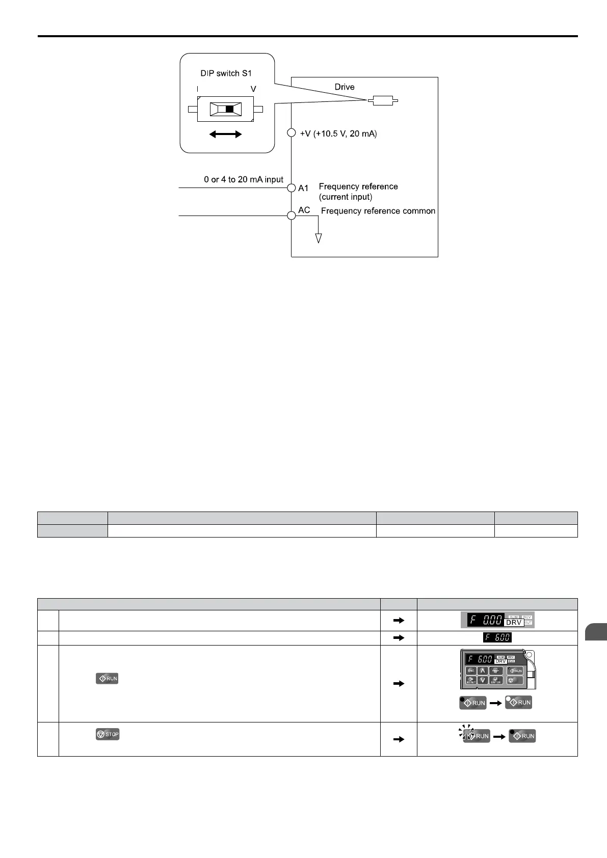
Figure 5.2 Setting the Frequency Reference by Current Input
Setting 2: MEMOBUS/Modbus Communications
Using
this setting, the frequency reference can be entered via RS-422/485 serial communications using the MEMOBUS/
Modbus protocol by using an optional SI-485/J Interface for MEMOBUS communication. Refer to Peripheral Devices
& Options on page 147. For details about the MEMOBUS/Modbus protocol, Refer to MEMOBUS/Modbus
Communications on page 185.
Note: If the frequency reference source is set for MEMOBUS/Modbus but a communication interface option is not installed, an oPE05
Programming Error will be displayed on the digital operator and the RUN command will not be accepted.
Setting 3: Potentiometer Option
Using this setting, the frequency reference can be set by a potentiometer mounted at the drive using an AI-V3/J
Potentiometer option unit. Refer to Peripheral Devices & Options on page 147 and the option unit documentation.
Note: If the frequency reference source is set for the potentiometer option (b1-01 = 3) but an option board is not installed, an oPE05 Programming
Error will be displayed on the digital operator and the RUN command will not be accepted.
n
b1-02: Run Command Selection
Parameter b1-02 determines the Run and Stop command source in the REMOTE mode.
WARNING! Sudden Movement Hazard. Clear personnel, secure equipment, and check sequence and safety circuitry before starting
the drive. Failure to comply could result in death or serious injury from moving equipment.
No. Parameter Name Setting Range Default
b1-02 Run Command Selection 0 to 2 1
Setting 0: Operator
Using
this setting, the RUN and STOP keys on the operator keypad will start and stop the motor. The LED in the LO/RE
key will be on to indicate that the Run command is assigned to the operator. The example below shows how the drive can
be operated if b1-02 is set to 0.
Step Display/Result
1. Turn on the power to the drive. The initial display appears.
2. Set the frequency reference to F6.00 (6 Hz).
3.
Press the key to start the motor. The RUN indicator LED will light and the motor
will begin rotating at 6 Hz.
STOP
off on
4.
Press the key to stop the motor. The RUN light will flash until the motor comes
to a complete stop.
flashing
off
Setting 1: Control Circuit Terminal
This
setting requires that the Run and Stop commands are entered from the digital input terminals. The following sequences
can be used:
5.2 b: Application
SIEP C710606 33A OYMC AC Drive – J1000 User Manual
73
5
Parameter Details