62 LD Platform OEM User's Guide 11970-000 Rev H1
6.2 Payload Bay Connections
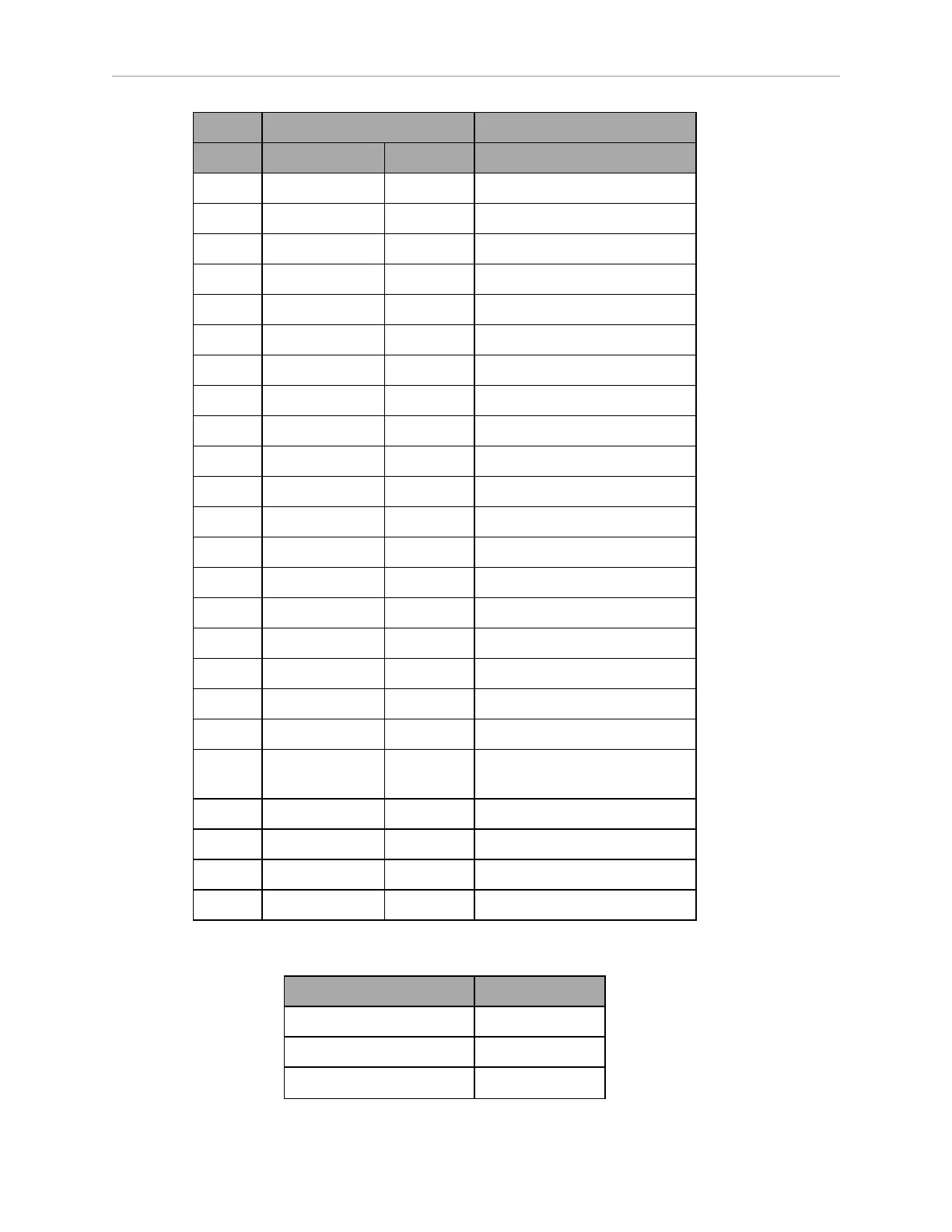
Designation
Pin No. Hardware Software Notes
18 INPUT_4.3 Input_4.3 0 – 30 V Range, R
in
= ~3.9 kΩ
19 INPUT_4.4 Input_4.4 0 – 30 V Range, R
in
= ~3.9 kΩ
20 BANK4 Common for INPUT_4.X
21 OUTPUT_1 Output_1
22 OUTPUT_2 Output_2
23 OUTPUT_3 Output_3
24 OUTPUT_4 Output_4
25 OUTPUT_5 Output_5
26 OUTPUT_6 Output_6
27 OUTPUT_7 Output_7
28 OUTPUT_8 Output_8
29 OUTPUT_9 Output_9
30 OUTPUT_10 Output_10
31 OUTPUT_11 Output_11
32 OUTPUT_12 Output_12
33 OUTPUT_13 Output_13
34 OUTPUT_14 Output_14
35 OUTPUT_15 Output_15
36 OUTPUT_16 Output_16
37 VBAT_IO_OUT4 VBAT @ 0.5 A Max
(shared with light pole)
38 VBAT_IO_OUT3 VBAT @ 0.5 A Max
39 VBAT_IO_OUT2 VBAT @ 0.5 A Max
40 VBAT_IO_OUT1 VBAT @ 0.5 A Max
41 - 44 GND
Digital Input Specifications
Parameter Value
Operational voltage range 0 to 30 VDC
OFF state voltage range 0 to 1.3 VDC
ON state voltage range 4 to 30 VDC