EasyManuals Logo

Omron LD Platform User Manual

Omron LD Platform
140 pages
To Next Page IconTo Next Page
To Previous Page IconTo Previous Page
Page #63 background imageLoading...
Page #63 background image
Chapter 6: Connectivity
Parameter Value
Operational current range 0 to 7.5 mA
OFF state current range 0 to 0.5 mA
ON state current range 1.0 to 7.5 mA
Impedance (V
in
/I
in
) 3.9 minimum
Current at V
in
= +24 VDC I
in
6 mA
NOTE:The input current specifications are provided for reference. Voltage sources
are typically used to drive the inputs.
Supplied Equipment
User-Supplied Equipment
Input_1.1
Part Present Sensor
1
Input_1.2
2
Input_1.3
3
Input_1.4
4
VBAT_IO_OUT1
GND
Bank 1
Common
Bank 4
Common
5
40
41
Input_4.1
16
Input_4.2
17
Input_4.3
18
Input_4.4
19
20
42
GND
37
VBAT_IO_OUT4
Wiring
Terminal
Block
Typical User
Input Signal
Note: all Input signals
can be used for either
sinking or sourcing
configurations.
Bank 1 configured for
Sinking (NPN) Inputs
Bank 4 configured for
Sourcing (PNP) Inputs
(equivalent circuit)
Input Bank 4
Input Bank 1
Input Bank 3
Input Bank 2
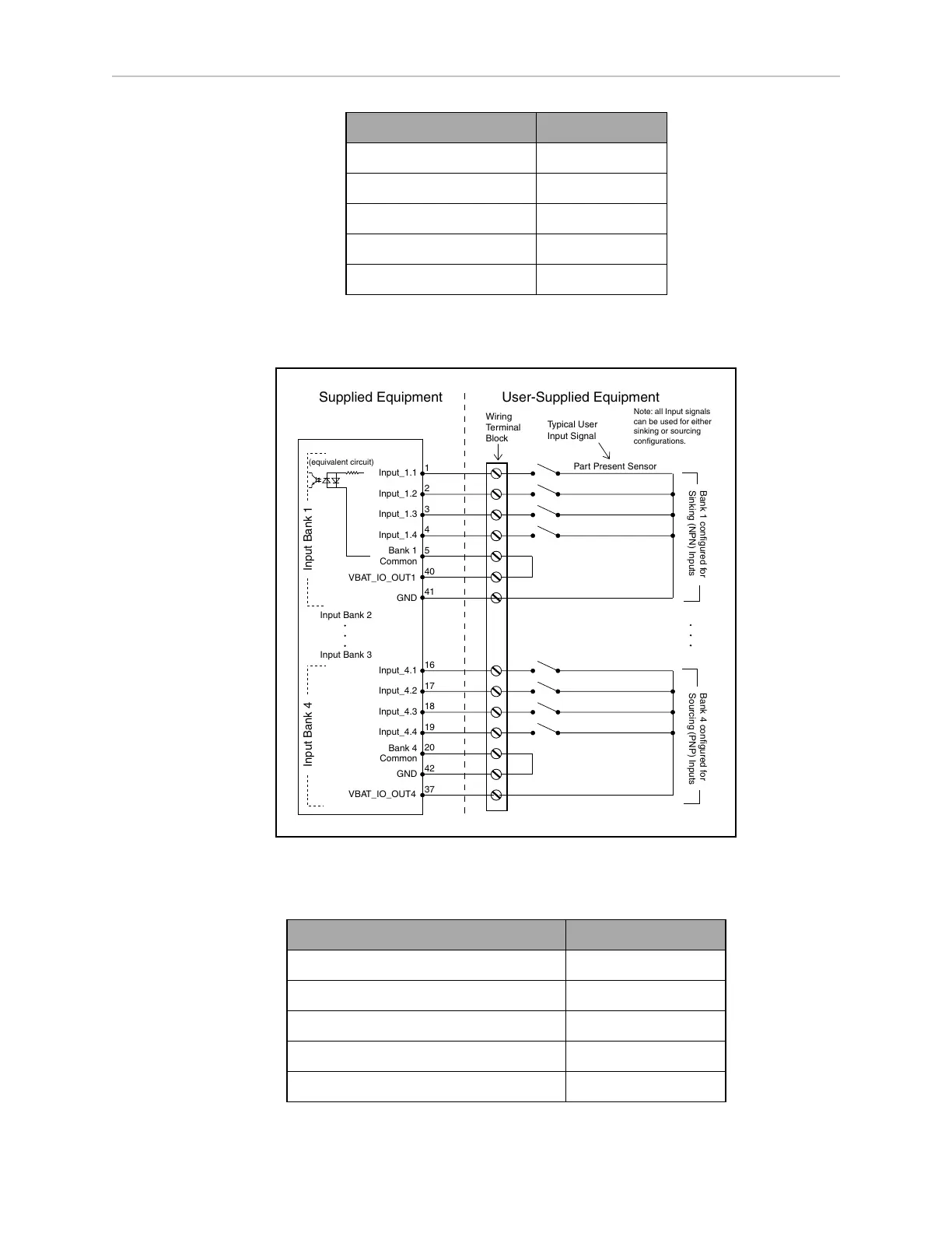
Figure 6-3. Typical Digital Input Wiring Example
Table 6-1. Digital Output Specifications
Parameter Value
Power supply voltage range 5 - 30 VDC
Operational current range, per channel I
out
500 mA
ON state resistance (I
out
= 0.5 A) R
on
0.14 Ω @ 85°C
Output leakage current I
out
5 μA
DC short circuit current limit 0.7 A I
LIM
1.7 A
11970-000 Rev H1 LD Platform OEM User's Guide 63

Table of Contents

Questions and Answers:

Question and Answer IconNeed help?

Do you have a question about the Omron LD Platform and is the answer not in the manual?

Omron LD Platform Specifications

General IconGeneral
BrandOmron
ModelLD Platform
CategoryRobotics
LanguageEnglish

Related product manuals