64 LD Platform OEM User's Guide 11970-000 Rev H1
6.2 Payload Bay Connections
Standard Equipment User-Supplied Equipment
Outputs 1-16
Typical User Loads
VBAT_IO_OUT1
VBAT_IO_OUT4
21
OUTPUT_1
22
OUTPUT_2
23
OUTPUT_3
24
OUTPUT_4
25
OUTPUT_5
36
OUTPUT_16
GND
Load
41
GND
44
Load
(equivalent
circuit)
Wiring Terminal Block
37
Load
40
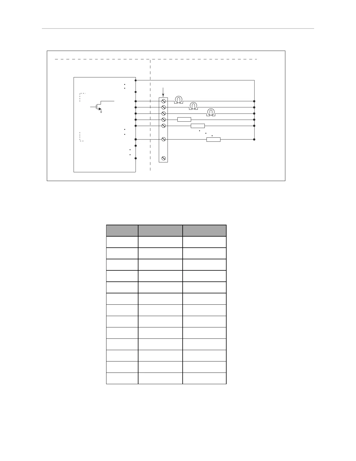
Figure 6-4. Typical Digital Output Wiring Example
Analog I/O
Connector type HDB15M
Pin No. Designation Notes
1 ANALOG_IN1 0 – 10 V Range
2 ANALOG_IN2 0 – 10 V Range
3 ANALOG_IN3 0 – 10 V Range
4 ANALOG_IN4 0 – 10 V Range
5 ANALOG_IN5 0 – 30 V Range
6 ANALOG_IN6 0 – 30 V Range
7 ANALOG_IN7 0 – 30 V Range
8 ANALOG_IN8 0 – 30 V Range
9 ANALOG_OUT1 0 – 20 V Range
10 ANALOG_OUT2 0 – 20 V Range
11 ANALOG_OUT3 0 – 20 V Range
12 ANALOG_OUT4 0 – 20 V Range
13, 14, 15 GND
l
The 0-10 V analog inputs have an input impedance of about 35 kΩ.
l
The 0-30 V analog inputs have an input impedance of about 110 kΩ.