Chapter 6: Connectivity
l
The analog outputs have an output impedance of about 200 Ω.
The maximum output current of each analog output is 10 mA. Exceeding the maximum
output current will result in damage to the analog output module.
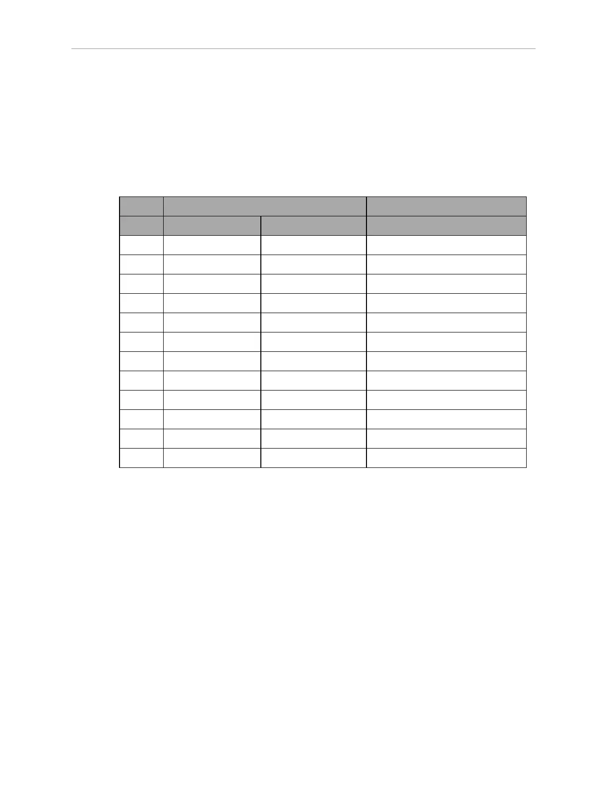
Aux Sensors
Connector type HDB15M
Use Low Front Laser, optional Side Lasers
Designation
Pin No. Hardware Software Notes
1 RS232_VERT1_TXD /dev/ttyUSB5 (side lasers)
2 RS232_VERT2_TXD /dev/ttyUSB6 (side lasers)
3 RS232_FOOT_TXD /dev/ttyUSB7 (low front laser)
4 5V_SW1 USB_1_and_2_Power 5 V @ 1 A (shared with USB port 1)
5, 10 SW_20V_VERT Vertical_Laser_Power 20 V @ 300 mA (side lasers)
6, 7, 8 GND
9 5V_SW2 USB_1_and_2_Power 5 V @ 1 A (shared with USB port 2)
11 RS232_VERT1_RXD /dev/ttyUSB5 (side lasers)
12 RS232_VERT2_RXD /dev/ttyUSB6 (side lasers)
13 RS232_FOOT_RXD /dev/ttyUSB7 (low front laser)
14 5V_SW3 USB_3_Power 5 V @ 1 A (shared with USB port 3)
15 SW_20V_FOOT Foot_Laser_Power 20 V @ 150 mA (low front laser)
11970-000 Rev H1 LD Platform OEM User's Guide 65