Chapter 6: Connectivity
Connection Type Description
OFF Pins for user-supplied OFF button; same function as Operator
Panel OFF
ESTOP Pins for user-supplied E-Stop (must be used or jumpered)
User
Bumpers
Mini-Fit
2 x 4
Payload structure bumpers, user-supplied, connected between
ESTOP_SRC and USER_BMP# (for each of the 6 inputs).
Contacts 1 - 3 are for a front bumper, 4 - 6 for rear.
Contacts should be 12 V @ 10 mA.
Aux Power Mini-Fit
2 x 3
5, 12, and 20 VDC Outputs
User Power Mini-Fit
2 x 6
Battery and switched battery power
Maint LAN RJ45,
Shielded
Directly connected to the externally-mounted Maintenance
Ethernet, Auto-MDIX.
Joystick DB9F Directly connected to the externally-mounted Joystick port
HMI Panel HDB15F Operator screen, E-Stop, Brake_Rel, ON, OFF
Sonar 2 DB9M Not used
Power Connections
The platform provides conditioned 5, 12, and 20 VDC, and raw (battery) 22 - 30 VDC power to
the platform’s and accessory electronics, including the onboard core and laser LIDAR (Light
Detection And Ranging).
All power connectors are Mini-Fit
®
.
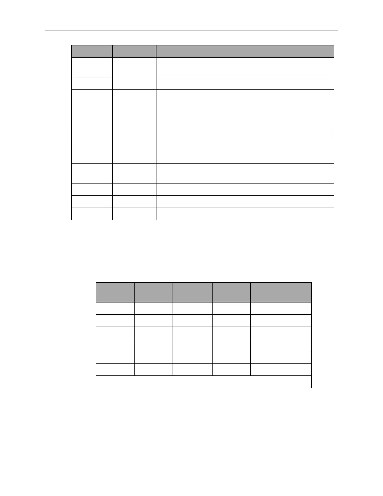
Nominal Qty Actual
Maximum
Current
Description
5 VDC 1 5 VDC±5% 1 A Switched Aux power
12 VDC 1 12 VDC±5% 1 A Switched Aux power
20 VDC 1 20 VDC±5% 1 A Switched Aux power
22 - 30 VDC 2 battery 4 A Switched
22 - 30 VDC 1* battery 10 A Switched
22 - 30 VDC 1* battery 10 A Safe, Switched
* 10 A Switched and 10 ASafe, Switched share the 10 A of current.
Each supply has an associated LED which, when lit, indicates that the port is actively
powered. See LD Platform Core Indicators on page 94.
The Safe 22 - 30 VDC supply automatically gets disconnected when the E-Stop button is
pressed, an obstacle is detected, or the bumper touches something.
11970-000 Rev H1 LD Platform OEM User's Guide 67