Chapter 6: Connectivity
User Bumper
NOTE:The User Bumpers connector is not safety-rated.
NOTE:Pins 1 through 3 are for a front-mounted bumper, 4 through 6 are for a rear-
mounted bumper.
Connector type Mini-Fit
®
4 x 2
Use Optional bumper for payload structure
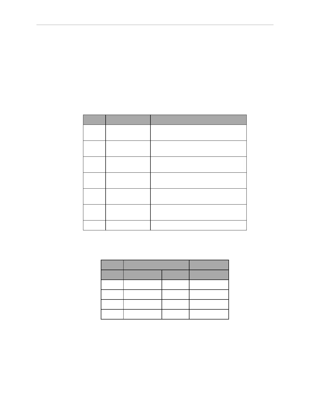
Pin No. Designation Notes
1 USER_BUMPER_1 Short to ESTOP_SRC to signal bumper hit
Front left bumper sensor.
2 USER_BUMPER_2 Short to ESTOP_SRC to signal bumper hit
Front center bumper sensor.
3 USER_BUMPER_3 Short to ESTOP_SRC to signal bumper hit
Front right bumper sensor.
4 USER_BUMPER_4 Short to ESTOP_SRC to signal bumper hit
Rear right bumper sensor.
5 USER_BUMPER_5 Short to ESTOP_SRC to signal bumper hit
Rear center bumper sensor.
6 USER_BUMPER_6 Short to ESTOP_SRC to signal bumper hit
Rear left bumper sensor.
7, 8 ESTOP_SRC 12 V ESTOP Source Output @ 10 mA
Aux Power
Connector type Mini-Fit
®
3 x 2
Designation
Pin No. Hardware Software Notes
1, 2, 3 GND
4 AUX_5V_OUT Aux_5V 5 V @ 1 A max
5 AUX_12V_OUT Aux_12V 12 V @ 1 A max
6 AUX_20V_OUT Aux_20V 20 V @ 1 A max
11970-000 Rev H1 LD Platform OEM User's Guide 71