72 LD Platform OEM User's Guide 11970-000 Rev H1
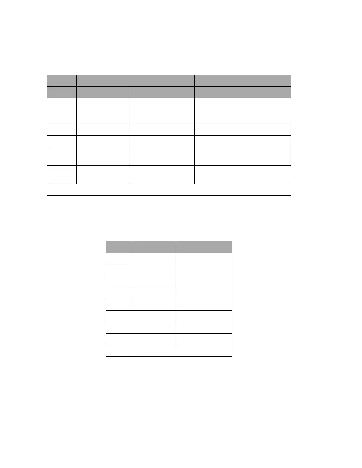
6.2 Payload Bay Connections
User Power
Connector type Mini-Fit
®
6 x 2
Designation
Pin No. Hardware Software Notes
1, 2,
3, 4,
5, 6
GND Limit to < 5 A per pin
7 SW_VBAT_OUT1 Battery_Out_1 VBAT @ 4 A max (switched in SW)
8 SW_VBAT_OUT2 Battery_Out_2 VBAT @ 4 A max (switched in SW)
9, 10* SW_VBAT_OUT34 Battery_Out_3_and_4 VBAT @ 10 A max (switched in SW)
Limit to < 5 A per pin.
11, 12* SAFE_VBAT_OUT SW_VBAT_OUT34 gated by
dual-channel ESTOP relays
*9,10 and 11,12 share the 10 A of current.
Joystick
Connector type DB9F
Use Joystick
Pin No. Designation Notes
1 JOY_XAXIS Analog X input
2 JOY_YAXIS Analog Y input
3 JOY_SPEED Analog SPEED input
4 JOY_GOAL Goal Button Input
5 JOY_EN_1H Enable channel 1
6 JOY_EN_2L Enable channel 2
7 No Connection
8 GND
9 5V 5 V @ 100 mA