2 - 7
2 Configuration Units
NA-series Programmable Terminal Hardware User’s Manual (V117)
2-1 NA Units
2
2-1-1 Components and Functions
• Connecting Devices That Support IEEE 802.3i (10BASE-T) or IEEE 802.3u (100BASE-TX)
• Connecting Devices That Support IEEE 802.3ab (1000Base-T)
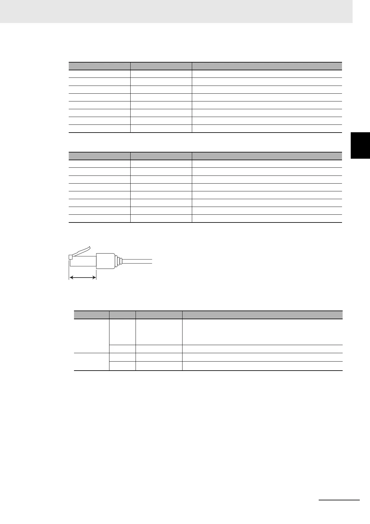
If you use a cable with a hood or boot, make sure that the mating length is at least 15 mm, as shown
in the following figure.
• Ethernet Port Indicators
Pin No. Signal name Name
1 TD+ Twisted-pair output (differential output)
2 TD- Twisted-pair output (differential output)
3 RD+ Twisted-pair input (differential input)
4 BI D+ Protection circuit
5 BI D- Protection circuit
6 RD- Twisted-pair input (differential input)
7 BI D+ Protection circuit
8 BI D- Protection circuit
Pin No. Signal name Name
1 TRD0+ Send/receive data 0+
2 TRD0- Send/receive data 0-
3 TRD1+ Send/receive data 1+
4 TRD2+ Send/receive data 2+
5 TRD2- Send/receive data 2-
6 TRD1- Send/receive data 1-
7 TRD3+ Send/receive data 3+
8 TRD3- Send/receive data 3-
Indicator Color Status Description
LINK --- Not lit. A link was not established.
• The cable is not connected.
• The power supply is OFF or the NA Unit was reset.
Green Lit. The link was established.
ACT --- Not lit. The link is on standby.
Orange Flashing. Data is being sent or received.

 Loading...