305
Fixed Displays
Section 7-4
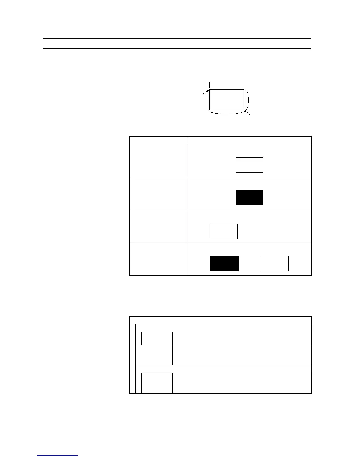
At the Support Tool, specify the start point and end point as shown in the figure
below (it is not necessary to draw the rectangle from top left to bottom right). By
setting the start point and end point, the position and size are automatically set.
Start point
Position (top left corner of the rectangle)
Size (Y direction)
Size (X direction)
End point
- Display attribute and drawing result
Attribute Drawing Result
Standard Only the boundary line of the rectangle is drawn in the
foreground color.
Inverse The entire rectangle is displayed in the foreground
color.
Flash Repeated alternation between “standard” display and
no display.
!
No display
Inverse Flash Repeated alternation between “inverse” and “standard”
display.
!
S Polygon
The relationship between the properties of apolygon and the displayedgraph-
ic are indicated below.
- Properties
General
Position
Attribute
Point
Coordinates of the point that will be the start position for tiling
in inverse display or inverse flashing display.
Attribute Display mode for the polygon (“Display attribute and drawing
result”, page 306).
Standard/Inverse/Flash/Inverse Flash
Color
Foreground Display color of the polygon (colors other than black and white
featured with NT31C only)
Black/Blue/Red/Magenta/Green/Cyan/Yellow/White
The line style is fixed as “solid line” and thickness is fixed as one dot.